
System for relieving lateral strain on a rod string within a wellbore

a wellbore and rod string technology, applied in the direction of drilling rods, drilling casings, drilling pipes, etc., can solve the problems of bore itself providing lateral strain on the sucker rod assembly, affecting the operation of the wellbore, etc., to achieve easy adjustment of the mechanism, relieve lateral strain, and reduce the effect of lateral strain

Active Publication Date: 2019-11-19
DOWNING RANDY
View PDF12 Cites 0 Cited by
  • Summary
  • Abstract
  • Description
  • Claims
  • Application Information

AI Technical Summary

Benefits of technology

The present invention is about a mechanism to reduce tension between adjacent sections of sucker rods in a wellbore. It uses a swivel mechanism that allows for lateral movement of the sucker rods, which helps to relieve the tension between them. The invention also includes a ball shank housing with a wider swivel gap to allow for swivel movement of the sucker rods. This reduces the stress between joints of the sucker rods. Additionally, the invention is about an adjustment rod adjuster that can easily adjust the interaction between a pump jack and a polished rod. This adjustor uses a load adjustment housing that can be adjusted at predefined increments to change the load bearing capacity. Overall, the invention improves the efficiency and stability of wellbore pumping operations.

Problems solved by technology

One of the typical problems with the prior art is that the hydrostatic pressure on the down pump in the prior art causes lateral and oscillating movement with pumping can result in the parting of sucker rods or polished rods, requiring a rig to come in and pull all the rods, replace the sucker rods with new rods.
All of this usually requires the well to be shut-in, costing time and money to the operator.
Therefore, the well bore itself may provide lateral strain on the sucker rod assembly as the wells pumping.
All this can cause the sections of sucker rods to wear out due to the lateral forces, and may also result in separating of adjacent rods or parting of rods along the threaded attachments between the adjacent rods.

Method used


Image

  • System for relieving lateral strain on a rod string within a wellbore
  • System for relieving lateral strain on a rod string within a wellbore
  • System for relieving lateral strain on a rod string within a wellbore

Examples


Embodiment Construction

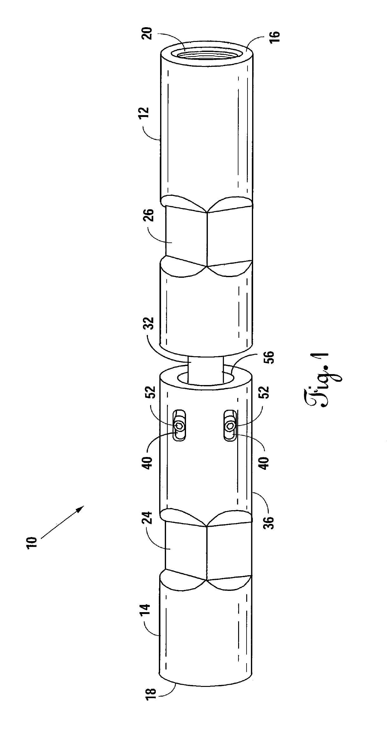
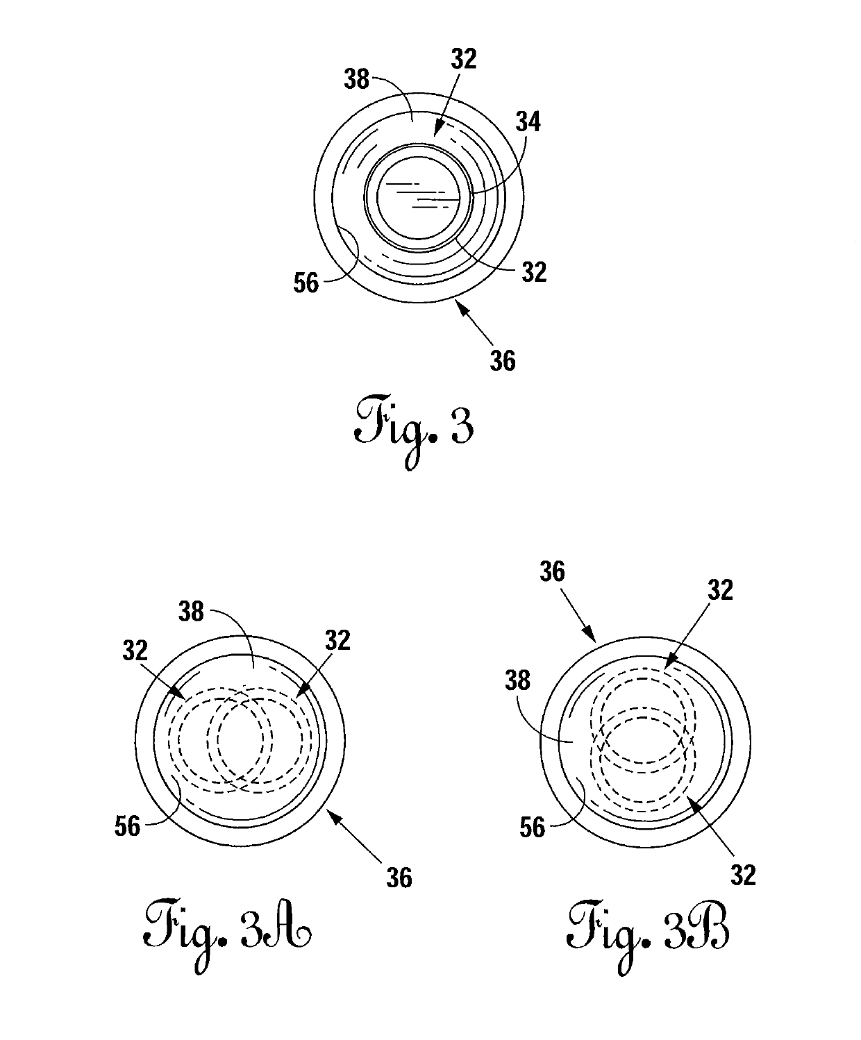
[0030]Referring to FIGS. 1 through 6, the system for relieving lateral stress placed on rods within a wellbore is disclosed. Referring to FIGS. 1 and 2, the preferred embodiment of the flexible sucker rod coupling 10 of present invention is disclosed. The flexible sucker rod coupling 10 comprises a top connecting member 12, a ball shank housing 36 for receiving a ball shank 32 therein, and a bottom connecting member 14. Referring to FIG. 2, the top connecting member 12 comprises a top end which, along the top edge defines a sucker rod connecting member 16. Sucker rod connecting member 16 comprises a recessed shoulder (not shown) along the top portion thereof, which receives an adjacent sucker rod inwards towards the interior of top connecting member 12, and terminates in a plurality of threads (not shown). The recess shoulder and threads of sucker rod connecting member 16 of top connecting member 12 are substantially similar to those shown as recessed shoulder 20 and threads defined...


PUM


Abstract

A system for relieving lateral stress on rods within a wellbore. A flexible sucker rod coupling has a top connecting member threadedly attached to a ball shank housing. The ball shank housing houses in a ball and socket fashion, a ball shank which extends out of the ball shank housing, defining a swivel gap to allow swivel movement. The ball shank is threadedly attached to a lower connection member. Both ends of the coupling threadedly attaches to an adjacent sucker rod within the wellbore. The ball shank is secured to the ball shank housing to ensure that the ball shank and the ball shank housing rotate together.

Description

[0001]This is a utility patent application claiming priority to U.S. provisional patent application No. 62 / 394,032 filed Sep. 13, 2016 and U.S. provisional patent application No. 62 / 394,053 filed Sep. 13, 2016.BACKGROUNDField of the Invention[0002]The present application relates to a system for relieving lateral strain on a rod string within a wellbore, and more particularly to sucker rod assembly used inside the tubing of a well bore. In one aspect, the present invention provides a multi-pieced sucker rod assembly that provides relief from lateral strain imparted on adjacent sucker rod sections by providing a predetermined degree of swivel between said sections. The present invention can be utilized as a single unit, or multiple units may be placed along the sucker rod string of a well, to alleviate lateral forces and stresses on adjacent sucker rods where desired or needed. In one aspect of the invention, the sucker rod assembly is designed to threadedly attach directly to adjacen...

Claims


Application Information

Patent Timeline
Patent Type & Authority Patents(United States)
IPC IPC(8): E21B17/02E21B17/10E21B17/20
CPCE21B17/02E21B17/20E21B17/1071E21B17/042
Inventor DOWNING, RANDY
Owner DOWNING RANDY
Learn More