
System and method for automated monitoring of fetal head descent during labor

a technology of automatic monitoring and fetal head descent, applied in the field of imaging, can solve the problems of high inter-observer variability, subjective digital examination, user-dependent and time-consuming methods,

Active Publication Date: 2019-11-19
GENERAL ELECTRIC CO
View PDF31 Cites 0 Cited by
  • Summary
  • Abstract
  • Description
  • Claims
  • Application Information

AI Technical Summary

Benefits of technology

The patent text describes a method for automatically monitoring fetal head descent during labor using images obtained from a birth canal. The method involves segmenting each image into smaller parts and calculating a cost function for each segment. Based on these calculations, the method identifies specific structures of interest in the images, such as the pubic ramus and fetal head, and measures the angle at which the fetal head descends. This angle is then used to determine the overall location of the fetal head in the birth canal. The invention provides a non-transitory computer-readable medium and an imaging system for this purpose. The technical effect of the patent is to provide a reliable and automated method for measuring fetal head descent in labor, which could help improve obstetric outcomes and reduce the risk of complications.

Problems solved by technology

Unfortunately, the digital examination is subjective and inaccurate with high inter-observer variability.
However, manually measuring the angle of progression using the ultrasound images is a user-dependent and time-consuming method.
Moreover, there is substantial variability in the measurement of angle of progression and interpretation of fetal station even among experienced clinicians.
Consequently, this variability in the measurement of the angle of progression adversely affects clinical evaluation of the progress of labor.
However, these techniques disadvantageously call for manual marking of points on the pelvis or entail use of a position sensor followed by marking known fetal head landmarks on the ultrasound image to determine the spatial position of the fetal head in relation to the pelvic bone.
However, the need for manual intervention while using these techniques impedes the automation of the process of monitoring the fetal head descent during labor.

Method used


Image

  • System and method for automated monitoring of fetal head descent during labor
  • System and method for automated monitoring of fetal head descent during labor
  • System and method for automated monitoring of fetal head descent during labor

Examples


Embodiment Construction

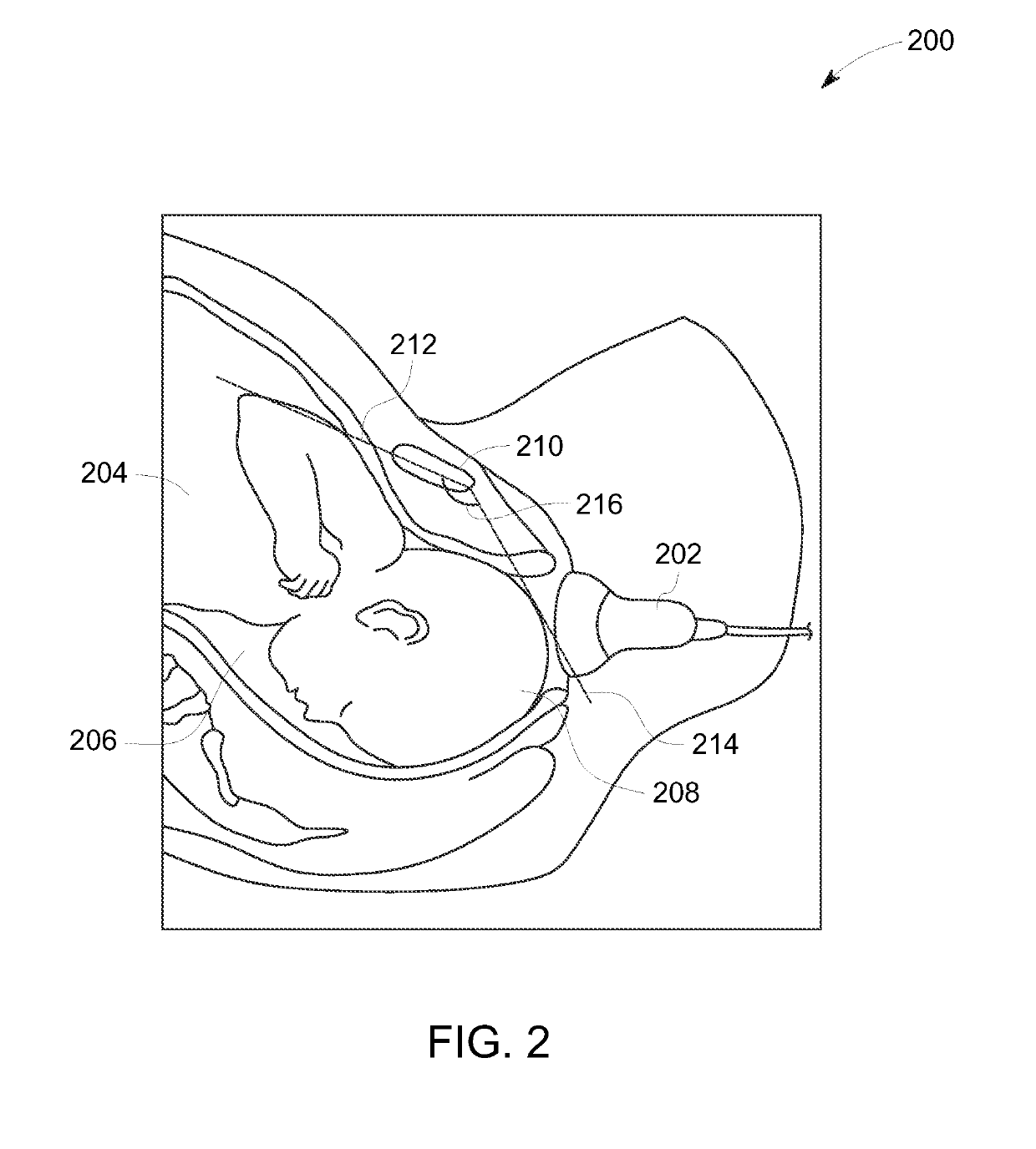
[0022]As will be appreciated, during the process of childbirth, a clinician, such as a physician or a midwife monitors descent of a fetal head in a birth canal of a patient in labor. In accordance with exemplary aspects of the present specification, systems and methods configured to aid in enhancing clinical workflow are presented. In particular, the methods and systems are configured to facilitate automated monitoring of the fetal head descent during labor. Additionally, the systems and methods provide an objective and reproducible tool for monitoring the fetal head descent, while reducing variability in assisting patients during labor.

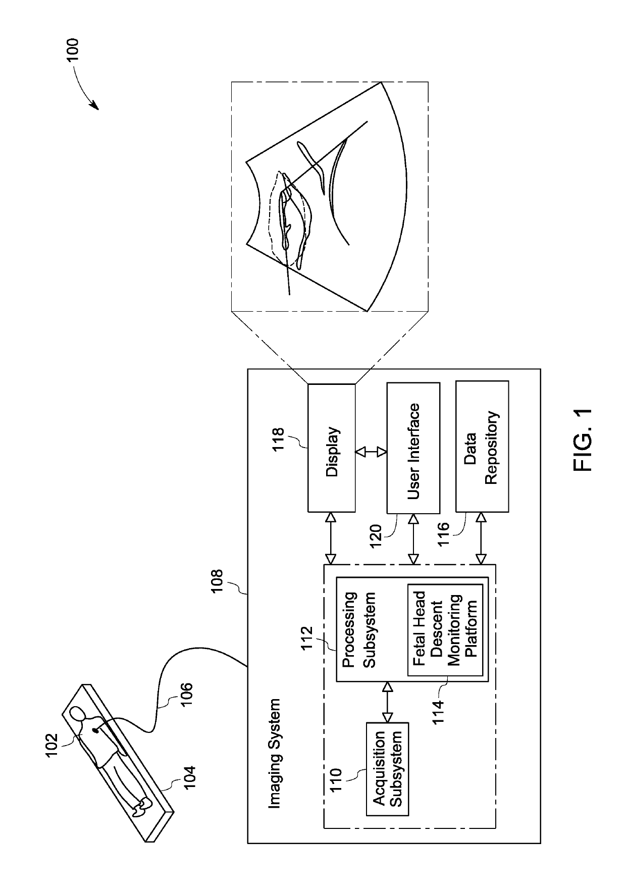
[0023]FIG. 1 is a block diagram of an exemplary system 100 for use in diagnostic imaging, in accordance with aspects of the present specification. More particularly, the system 100 is configured to aid the clinician in monitoring the fetal head descent in a birth canal of a patient 102 during labor.

[0024]During labor and delivery, the clinician, typi...


PUM


Abstract

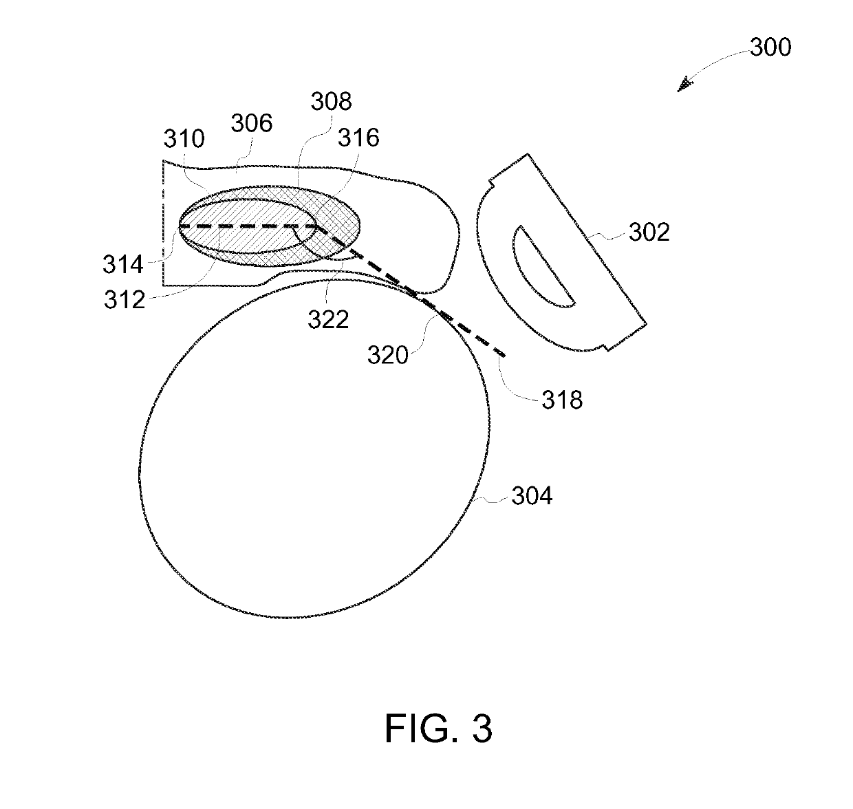
A method for automatically monitoring fetal head descent in a birth canal is presented. The method includes segmenting each image in one or more images into a plurality of neighborhood components, determining a cost function corresponding to each neighborhood component in the plurality of neighborhood components in each of the one or more images, identifying at least two structures of interest in each image in the one or more images based on the cost function, wherein the at least two structures of interest include a pubic ramus and a fetal head, measuring an angle of progression based on the at least two structures of interest, and determining the fetal head descent in the birth canal based on the angle of progression.

Description

BACKGROUND[0001]Embodiments of the present specification relate to imaging, and more particularly to automated measurement of fetal head descent in a birth canal during labor.[0002]Ultrasound imaging has been employed for a wide variety of applications. During the process of ultrasound scanning, a clinician attempts to capture a view of a certain anatomy which confirms / negates a particular medical condition. Once the clinician is satisfied with the quality of a view or a scan plane, the image is frozen to proceed to a measurement phase. For example, ultrasound images are routinely used to assess gestational age (GA) and weight of a fetus or to monitor cardiac health of a patient. Subsequent to the selection of a desired image, ultrasound measurements of specific features of fetal anatomy such as the head, abdomen or the femur from two-dimensional (2D) or three-dimensional (3D) image data may be obtained. These measurements are used in the determination of GA, assessment of growth pa...

Claims


Application Information

Patent Timeline
Patent Type & Authority Patents(United States)
IPC IPC(8): A61B8/08A61B5/11A61B5/00A61B5/107A61B5/055
CPCA61B5/1128A61B8/0866A61B5/1075A61B8/5223A61B5/4362A61B5/1122A61B2503/02A61B5/1079A61B5/055A61B2576/00G16H50/30
Inventor SINGHAL, NITINKRISHNAN, KAJOLI BANERJEEPERREY, CHRISTIAN FRITZPINTOFFL, KLAUSDUDA, JR., WALTERPATRUNO, FRANCESCA
Owner GENERAL ELECTRIC CO
Learn More