
Systems and methods for image pattern recognition

Active Publication Date: 2007-08-14
LEICA BIOSYST IMAGING
View PDF52 Cites 107 Cited by
  • Summary
  • Abstract
  • Description
  • Claims
  • Application Information

AI Technical Summary

Benefits of technology

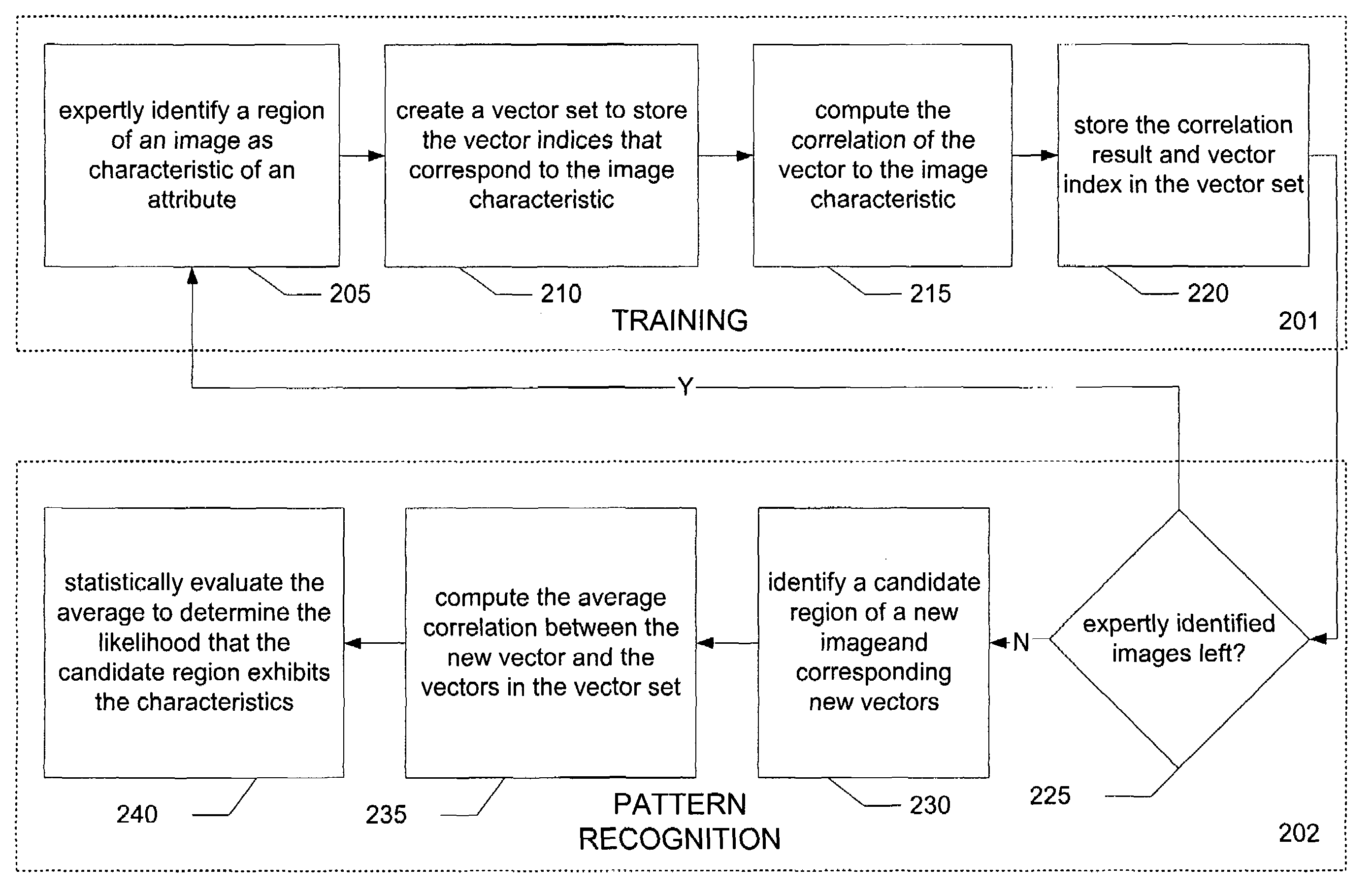
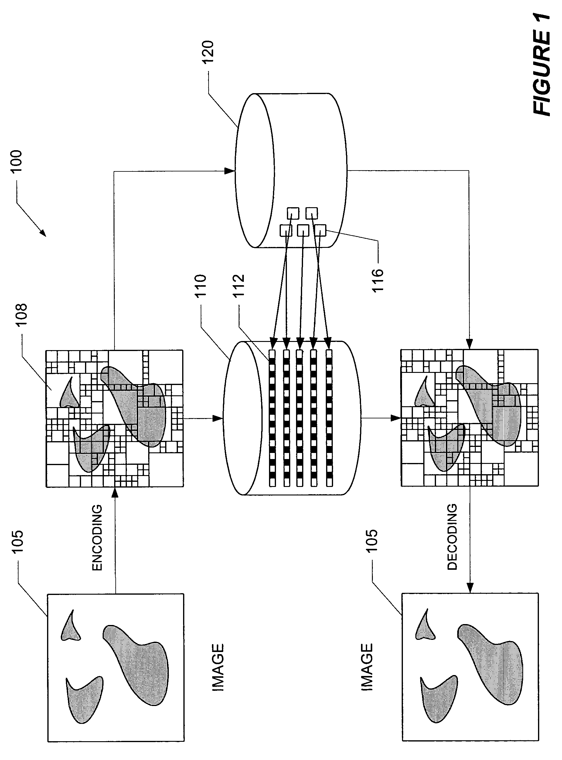
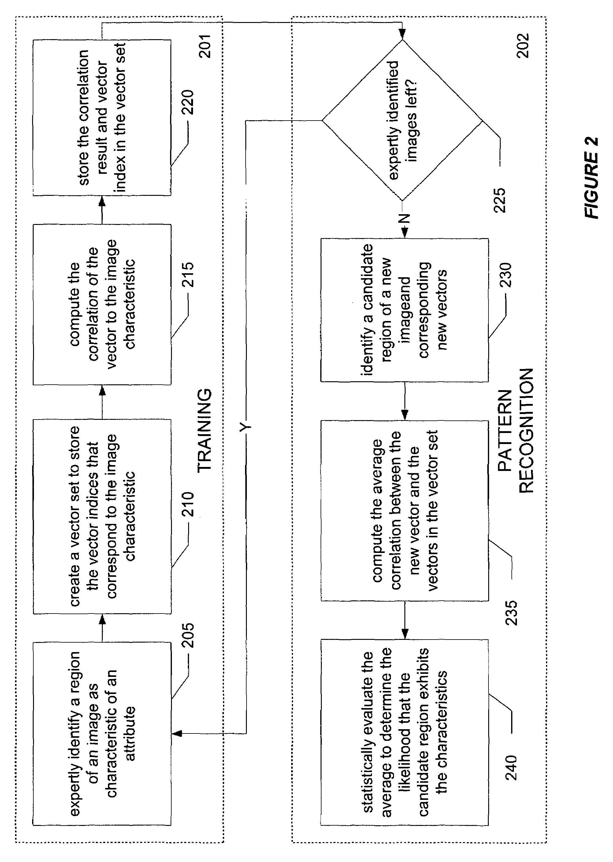
[0009]Systems and methods for image pattern recognition comprise digital image capture and encoding using vector quantization (“VQ”) of the image. A vocabulary of vectors is built by segmenting images into kernels and creating vectors corresponding to each kernel. Images are encoded by creating vector index files with indices (“pointers”) to the vectors stored in the vocabulary. The vector index files can be used to reconstruct the images by looking up vectors stored in the vocabulary. Pattern recognition of candidate regions of images can be accomplished by correlating image vectors to a pre-trained vocabulary of vector sets comprising vectors that correlate with particular image characteristics. In virtual microscopy, the systems and methods are suitable for rare-event finding, such as detection of micrometastasis clusters, tissue identification, such as locating regions of analysis for immunohistochemical assays, and rapid screening of tissue samples, such as histology sections arranged as tissue microarrays (TMAs).

Problems solved by technology

An obstacle to automating microscopic inspection has been the inability to efficiently digitize entire microscope specimens at diagnostic resolutions.
First, images frequently have distortion because image tiles are limited to a single focal plane from the camera's fixed area objective lens.
Second, an image tiling system produces optical aberrations that are circularly symmetric about the center of the image tile.
Third, full pixel resolution is usually unavailable because color CCD cameras lose spatial resolution upon interpolation of color values from non-adjacent pixels.
Conventional approaches to pattern recognition are also cumbersome.
These conventional approaches, however, are immensely complicated or completely untenable for histology imagery data where reliable object segmentation is difficult.

Method used


Image

  • Systems and methods for image pattern recognition
  • Systems and methods for image pattern recognition
  • Systems and methods for image pattern recognition

Examples


Embodiment Construction

[0021]Certain embodiments as disclosed herein provide for pattern recognition systems and methods. For example, one method as disclosed herein allows for a digitized image to be segmented into a plurality of image kernels. The image kernels are then analyzed to determine the intensity of each pixel in the kernel. The pixel intensities for an image kernel are then combined into a vector and the vector is stored in a data structure with other vectors for the image. Each vector is indexed to create a composite index for the digitized image that can later be reconstructed using the indices and the vectors.

[0022]After reading this description it will become apparent to one skilled in the art how to implement the invention in various alternative embodiments and alternative applications. However, although various embodiments of the present invention will be described herein, it is understood that these embodiments are presented by way of example only, and not limitation. As such, this deta...


PUM


Abstract

Systems and methods for image pattern recognition comprise digital image capture and encoding using vector quantization (“VQ”) of the image. A vocabulary of vectors is built by segmenting images into kernels and creating vectors corresponding to each kernel. Images are encoded by creating a vector index file having indices that point to the vectors stored in the vocabulary. The vector index file can be used to reconstruct an image by looking up vectors stored in the vocabulary. Pattern recognition of candidate regions of images can be accomplished by correlating image vectors to a pre-trained vocabulary of vector sets comprising vectors that correlate with particular image characteristics. In virtual microscopy, the systems and methods are suitable for rare-event finding, such as detection of micrometastasis clusters, tissue identification, such as locating regions of analysis for immunohistochemical assays, and rapid screening of tissue samples, such as histology sections arranged as tissue microarrays (TMAs).

Description

RELATED APPLICATION[0001]This application claims priority to U.S. Provisional patent application, Ser. No. 60 / 451,083 filed on Feb. 28, 2003, which is incorporated herein by reference in its entirety.BACKGROUND[0002]1. Field of the Invention[0003]The present invention generally relates to automated inspection of digitized microscope slides and more particularly relates to pattern recognition techniques employed in automated inspection of virtual slides.[0004]2. Related Art[0005]An obstacle to automating microscopic inspection has been the inability to efficiently digitize entire microscope specimens at diagnostic resolutions. Conventional approaches for creating virtual slides have relied on image tiling. Image tiling involves the capture of multiple, small regions of a microscope slide using a traditional charge coupled device (“CCD”) camera. These tiles are typically “stitched” together (aligned) to create a large contiguous digital image (mosaic) of an entire slide. A minimum of ...

Claims


Application Information

Patent Timeline
IPC IPC(8): G06K9/36G06T9/00G06T9/40G06V10/762H04N7/26H04N19/94
CPCG06K9/00147G06K9/6218H04N19/94G06T9/40H04N19/96G06T9/008G06V20/698G06V10/762G06F18/23
Inventor EICHHORN, OLESOENKSEN, DIRK G.
Owner LEICA BIOSYST IMAGING
Learn More