Flexible electroluminescent display device
a display device and flexible technology, applied in static indicating devices, instruments, organic semiconductor devices, etc., can solve the problems of increased process time and manufacturing costs, abnormal display functions or touch functions, etc., and achieve the effect of reducing one mask process and reducing stress applied
- Summary
- Abstract
- Description
- Claims
- Application Information
AI Technical Summary
Benefits of technology
Problems solved by technology
Method used
Image
Examples
first embodiment
[0058]A flexible electroluminescence display device according to the present disclosure will be described with reference to FIGS. 5 to 6B.
[0059]FIG. 5 is a plan view showing a first embodiment of the flexible electroluminescence display device shown in FIG. 4. FIG. 6A is a cross-sectional view taken along line I-I′ of FIG. 5. FIG. 6B is a cross-sectional view taken along line II-II′ of FIG. 5.
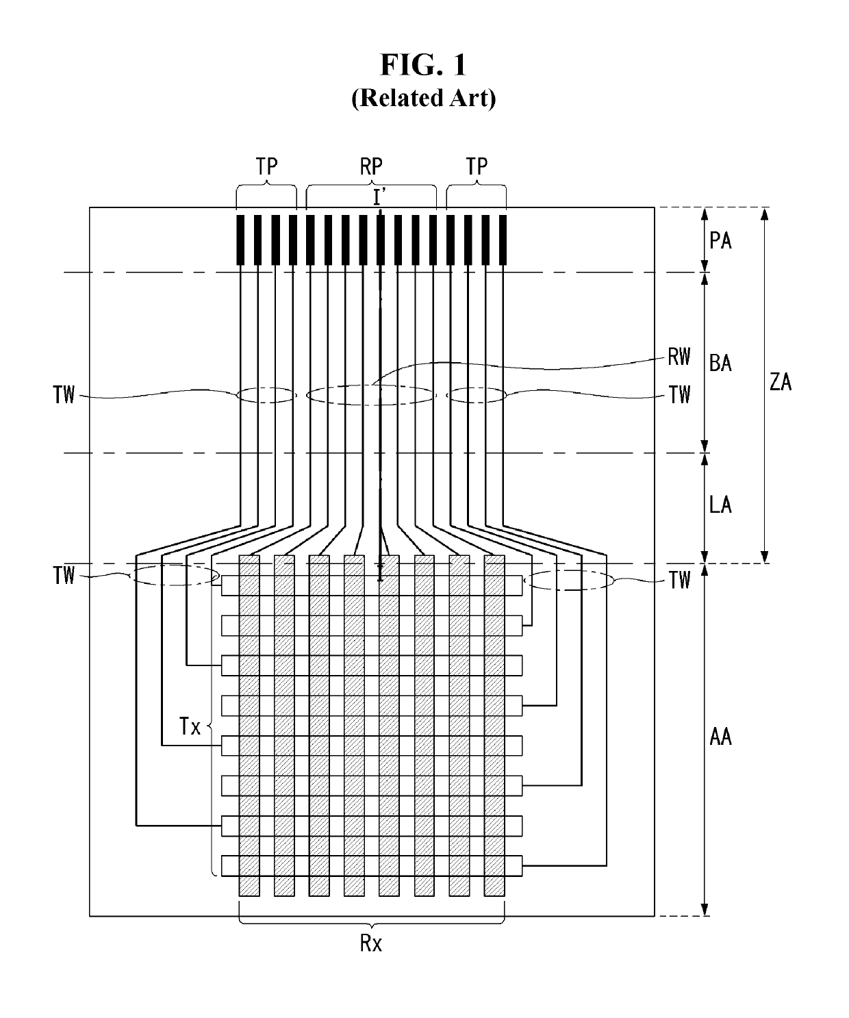
[0060]The flexible electroluminescent display device according to the first embodiment of the present disclosure may include an active area AA and a bezel area ZA outside the active area AA. The example of FIG. 6A illustrates a configuration of a data line DL and a data pad DP arranged in an active area AA and a bezel area ZA. The bezel area ZA includes a link area LA, a bending area BA, and a pad area PA.
[0061]The active area AA may be an area in which an input image is displayed and information is input through a touch or proximity of an object, such as a finger or a stylus pen. There may be ...
second embodiment
[0075]A flexible electroluminescence display device according to the present disclosure will be described with reference to FIGS. 7 to 8B.
[0076]FIG. 7 is a plan view showing a second embodiment of the flexible electroluminescence display device shown in FIG. 4. FIG. 8A is a cross-sectional view taken along line I-I′ of FIG. 7. FIG. 8B is a cross-sectional view taken along line II-II′ of FIG. 7.
[0077]A flexible electroluminescent display device according to the second embodiment of the present disclosure may include an active area AA and a bezel area ZA outside the active area AA. The example of FIG. 8A illustrates a configuration of a data line DL, a data link pattern DLP, and a data pad DP arranged in the active area AA and the bezel area ZA. The bezel area ZA may include a link area LA, a bending area BA, and a pad area PA.
[0078]The active area AA may be an area in which an input image is displayed and information is input through a touch or proximity of an object such as a finger...
third embodiment
[0093]A flexible electroluminescence display device according to the present disclosure will be described with reference to FIGS. 9 to 10B.
[0094]FIG. 9 is a plan view showing a third embodiment of the flexible electroluminescence display device shown in FIG. 4. FIG. 10A is a cross-sectional view taken along line I-I′ of FIG. 9. FIG. 10B is a cross-sectional view taken along line II-II′ of FIG. 9.
[0095]The FIG. 10A example illustrates a configuration of a data line DL, first and second data link patterns DLP1 and DLP2, and a data pad DP arranged in the active area AA and the bezel area ZA. The FIG. 10B example illustrates a second routing wire RW and a second touch pad RP in the bezel area ZA connected to a second touch electrode Rx disposed in the active area AA.
[0096]A flexible electroluminescent display device according to the third embodiment of the present disclosure includes an active area AA and a bezel area ZA outside the active area AA. The bezel area ZA may include a link a...
PUM
 Abstract
Description
Claims
Application Information
 - R&D
- Intellectual Property
- Life Sciences
- Materials
- Tech Scout
- Unparalleled Data Quality
- Higher Quality Content
- 60% Fewer Hallucinations
Browse by: Latest US Patents, China's latest patents, Technical Efficacy Thesaurus, Application Domain, Technology Topic, Popular Technical Reports.
© 2025 PatSnap. All rights reserved.Legal|Privacy policy|Modern Slavery Act Transparency Statement|Sitemap|About US| Contact US: help@patsnap.com


