
Electrical connector having an improved isolation block

a technology of isolation block and electric connector, which is applied in the direction of electrically conductive connections, coupling device connections, electrical apparatus, etc., can solve problems such as short circuit risk, and achieve the effect of avoiding short circui

Active Publication Date: 2019-11-05
FOXCONN INTERCONNECT TECH LTD
View PDF23 Cites 5 Cited by
  • Summary
  • Abstract
  • Description
  • Claims
  • Application Information

AI Technical Summary

Benefits of technology

The isolation block effectively prevents short circuits by maintaining a vertical separation between the metal shell and the conductive terminals, enhancing the reliability and safety of the electrical connector by avoiding unwanted electrical connections.

Problems solved by technology

The side wall of the metal shell is close to the soldering portion of the conductive terminal extending outwardly from the side edge of the insulating housing, not isolated from each other such that there is risk of short circuiting when the two are in contact.

Method used


Image

  • Electrical connector having an improved isolation block
  • Electrical connector having an improved isolation block
  • Electrical connector having an improved isolation block

Examples


Embodiment Construction

[0018]Reference will now be made in detail to the embodiments of the present disclosure. The direction of the conductive terminals arranged is a lengthwise direction.

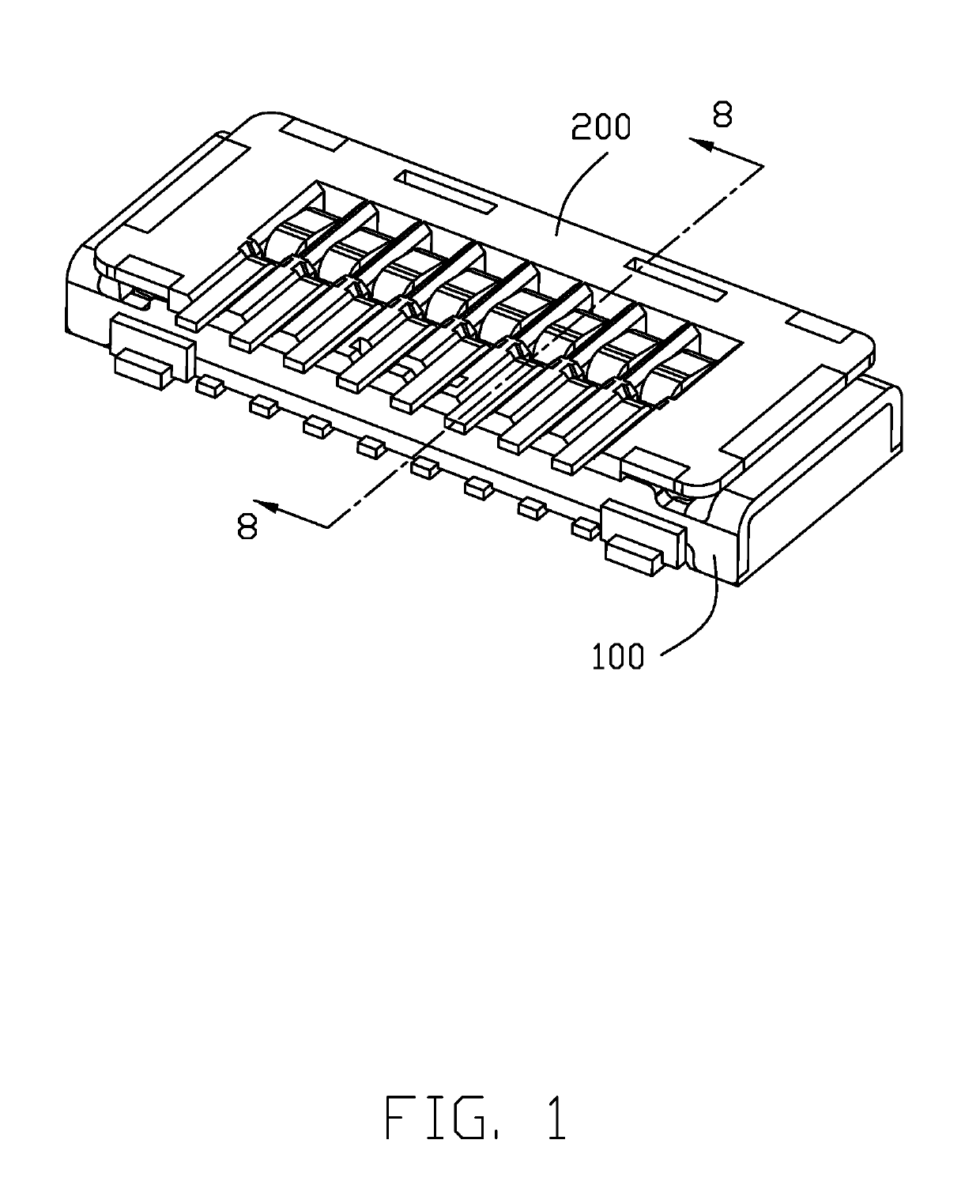
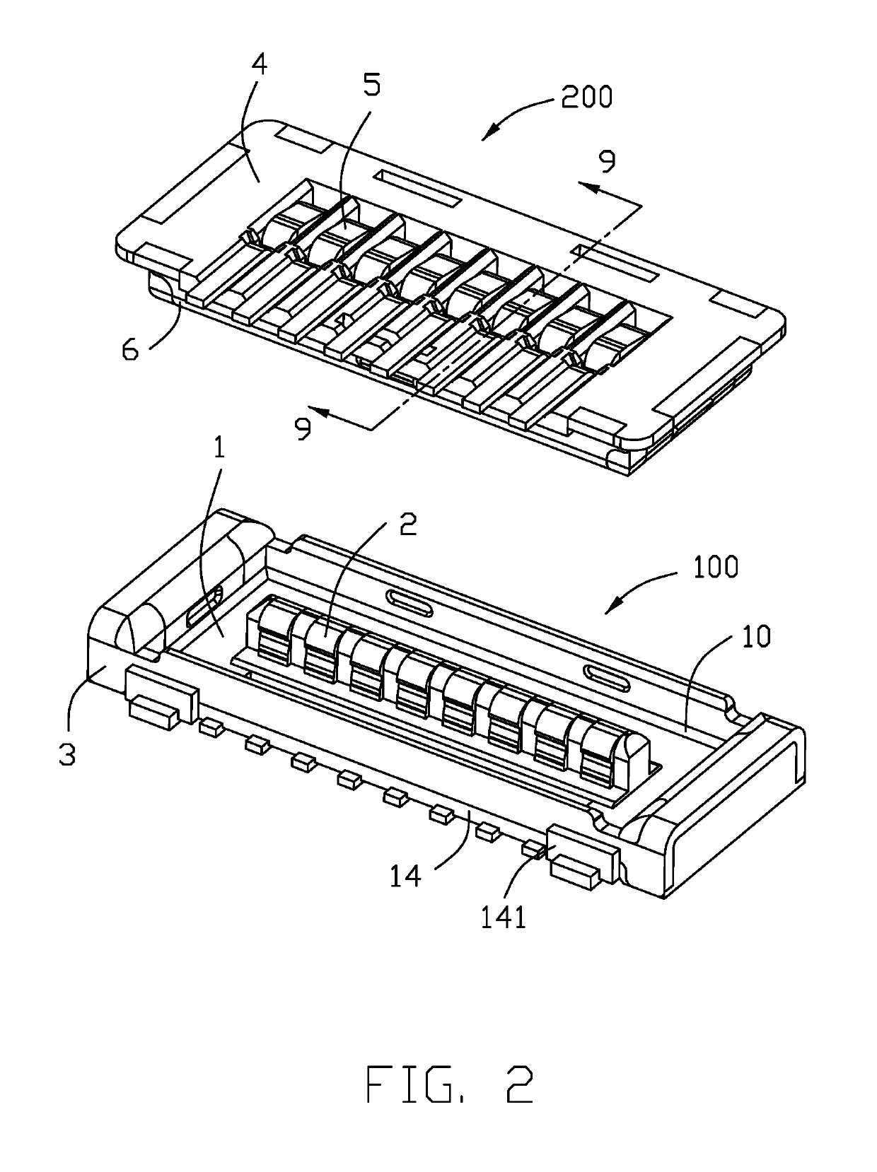
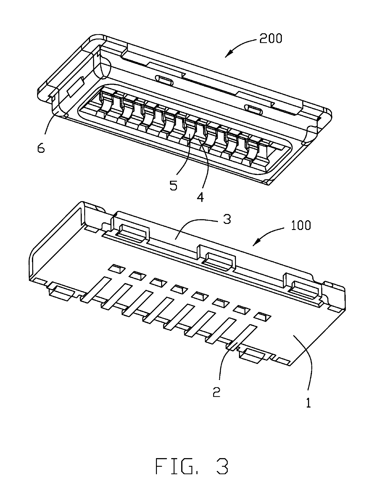
[0019]Referring to FIGS. 1-3 and 8-9, a first electrical connector 100 is shown for soldering on a printed circuit board and a second electrical connector 200 is shown for soldering on another printed circuit board. The first electrical connector 100 is mated with the second electrical connector 200.

[0020]Referring to FIGS. 4 to 5, the first electrical connector 100 includes a first insulative housing 1, a number of first conductive terminals 2 affixed to the first insulative housing 1, and a first metal shell 3 enclosing the first insulative housing 1.

[0021]Referring to FIGS. 4-5 and 8-9, the first insulative housing 1 includes a first base portion 12, a tongue portion 11 extending upwardly from the first base portion 12, a pair of end portions 13 isolated from each other in the lengthwise direction, and a first isolat...


PUM


Abstract

An electrical connector for soldering to a printed circuit board includes an insulative housing, a number of conductive terminals affixed to the insulative housing, and a metal shell surrounding the base portion. The insulative housing includes a base portion. Each conductive terminal includes a soldering portion extending laterally and outwardly from a lateral edge of the base portion. The metal shell includes a pair of longitudinal wall. The electrical connector includes an isolation block isolating the soldering portion from the longitudinal wall of the metal shell in a vertical direction.

Description

BACKGROUND OF THE DISCLOSURE[0001]1. Field of the Disclosure[0002]The present disclosure relates to an electrical connector, and more particularly to an electrical connector which can avoid short circuit caused by contacting between a soldering pin of a metal shell and a soldering portion of a conductive terminal.[0003]2. Description of Related Arts[0004]Taiwan Utility Model M539713 discloses an electrical connector assembly including a male end connector and a female end connector structurally modified to design a joint structure to ensure effective engagement of the male end connector with the female end connector. Due to the design of the joint structure, the male end connector and the female end connector can be effectively joined when the contact area is insufficient so that the joint height between the male end connector and the female end connector can be reduced and applicable to all kinds of small electronic devices. The metal shell of the board-to-board connector is direct...

Claims


Application Information

Patent Timeline
Patent Type & Authority Patents(United States)
IPC IPC(8): H01R13/6585H01R12/57H01R12/70H01R12/71H01R4/02H01R13/6594H01R24/60H01R107/00
CPCH01R13/6594H01R4/02H01R12/707H01R12/716H01R13/6585H01R12/57H01R4/028H01R24/60H01R2107/00
Inventor CHEN, CHIN-YU
Owner FOXCONN INTERCONNECT TECH LTD
Learn More