
Inlet manifold arrangement for a four-stroke combustion engine

a four-stroke combustion engine and manifold technology, which is applied in the direction of combustion-air/fuel-air treatment, air intake for fuel, functional valve types, etc., can solve the problems of increasing noise restriction regulations for combustion engines, occupying a large amount of space which cannot be provided, and reducing the noise level of combustion engines. , to achieve the effect of limiting the loss of power of combustion engines and reducing the noise levels of combustion engines

Active Publication Date: 2019-11-05
KTM AG
View PDF20 Cites 0 Cited by
  • Summary
  • Abstract
  • Description
  • Claims
  • Application Information

AI Technical Summary

Benefits of technology

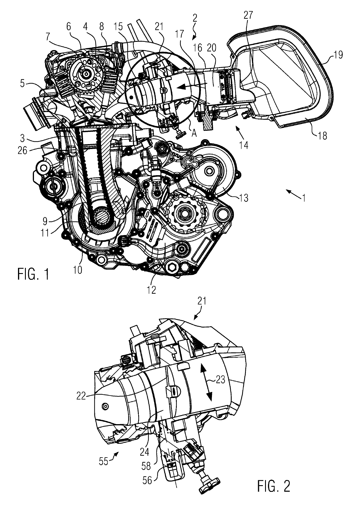
This patent describes a way to reduce the noise of a combustion engine and prevent a loss of power. It also explains how to use this arrangement on a motorcycle with limited space. The goal is to provide a quieter and more powerful motorcycle with a better engine performance. The invention aims to reduce the noise from the throttle valve, and the method uses the arrangement described in this patent to achieve this.

Problems solved by technology

Combustion engines are subject to ever increasing noise restriction regulations, which are relevant to their approval and have to be met, for example, in the type approval of a vehicle being approved for road transport.
The rolling noise of the tires of the vehicle also contributes to the overall noise level, and finally the intake noises of the combustion engine also form part of the overall noise pattern.
The intake noise of the combustion engine can be reduced using large-volume intake silencers in the intake area of the combustion engine, but these occupy a large amount of space which cannot be provided in the case of motorcycles, for example, for reasons related to their design.
In addition, the intake noise damping is often associated with an undesirable loss of power in the combustion engine, or with a reduction of the engine torque delivered by the combustion engine in different speed ranges.

Method used


Image

  • Inlet manifold arrangement for a four-stroke combustion engine
  • Inlet manifold arrangement for a four-stroke combustion engine
  • Inlet manifold arrangement for a four-stroke combustion engine

Examples


Embodiment Construction

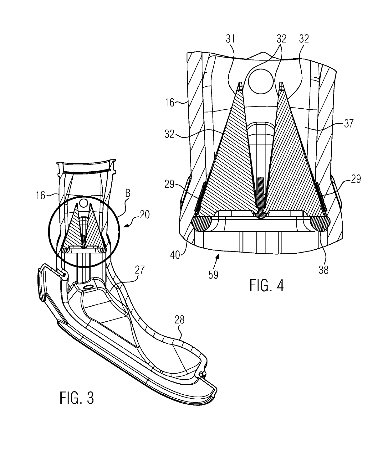
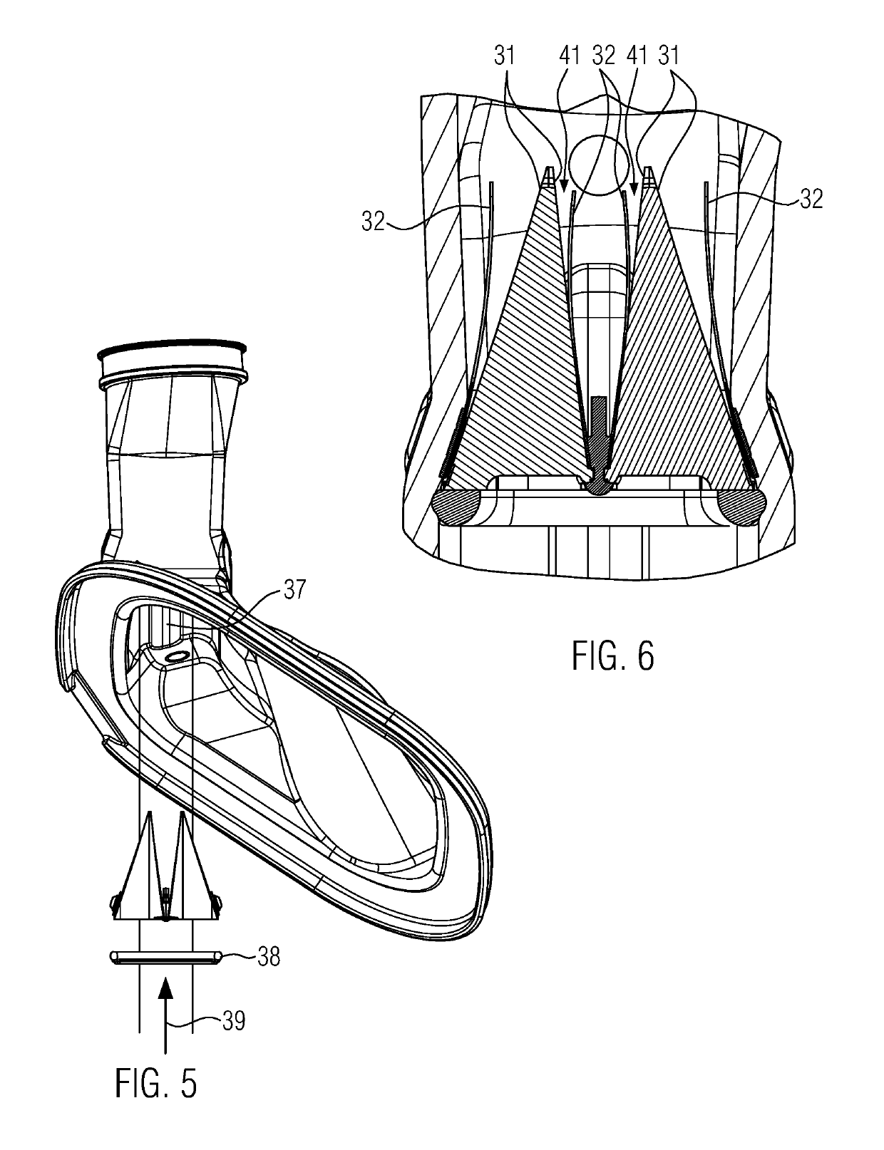
[0029]The drawing figures show a four-stroke combustion engine with an inlet manifold arrangement according to one embodiment of the presently disclosed apparatus and system. There is disclosed an apparatus with an inlet manifold arrangement for a four-stroke combustion engine having at least one working cylinder with inlet and outlet valves, and having an inlet manifold assembly which has a flow direction in the inlet direction and an end section adjacent to an air filter device. The apparatus has a throttle valve arrangement and a non-return valve which blocks in the direction opposite to the flow, wherein the non-return valve is arranged in the flow direction between the end section of the inlet manifold assembly and the throttle valve arrangement. The non-return valve thus is a sort of check valve, which prevents a backflow of fluid in a direction opposite to the flow of fluid (e.g., a fuel-air mixture) toward an inlet valve of the at least one working cylinder.

[0030]Stated diff...


PUM


Abstract

An inlet manifold arrangement is disclosed for a four-stroke internal combustion engine having at least one working cylinder with inlet valves and outlet valves and an inlet manifold assembly. The inlet manifold assembly has a flow direction for fluid (such as a fuel-air mixture) in the inlet direction, and an end section near an air filter device. The manifold assembly also has a throttle valve arrangement and a non-return valve which blocks in the direction opposite to the flow direction. The non-return valve is situated, in relation to the flow direction, between the end section of the inlet manifold assembly and the throttle valve arrangement.

Description

BACKGROUND OF THE INVENTIONField of the Invention[0001]The present invention relates to an inlet manifold arrangement for a four-stroke combustion engine having at least one working cylinder with inlet and outlet valves, and particularly relates to a manifold arrangement having an inlet manifold assembly which has a flow direction for fluid in the inlet direction and an end section adjacent to an air filter device.Background of the Invention[0002]A combustion engine usually comprises an inlet manifold arrangement with which a fuel-air mixture, or in the case of a combustion engine operated with direct fuel injection, intake air or combustion air is fed, in order to be introduced into the combustion chamber of the working cylinder through the open inlet valves.[0003]The inlet manifold arrangement can comprise a manifold assembly which contains a plurality of manifold segments. The manifold segments can be lengths of pipe of any cross-section and diameter, extending either straight or...

Claims


Application Information

Patent Timeline
Patent Type & Authority Patents(United States)
IPC IPC(8): F02M35/10F02M35/104F02M35/16F16K15/16F16K27/02
CPCF02M35/1015F02M35/10255F16K27/0209F16K15/16F02M35/104F02M35/162
Inventor ARNOLD, DAVIDDE COSTER, ROGERSPERZ, CHRISTIANHUBMANN, MARCOVIERTLMAYR, MICHAEL
Owner KTM AG
Learn More