In-vehicle solar charge control system, in-vehicle solar charge control method, and program

a technology of solar energy and control system, which is applied in the direction of battery/fuel cell control arrangement, light to electrical conversion, transportation and packaging, etc., can solve the problems of in-vehicle solar energy control system, large loss of power, and large power consumption of auxiliary machines supplied with the power from the first battery

Pending Publication Date: 2022-08-18
TOYOTA JIDOSHA KK
View PDF0 Cites 0 Cited by
  • Summary
  • Abstract
  • Description
  • Claims
  • Application Information

AI Technical Summary

Benefits of technology

The in-vehicle solar charge control system, method, and program described in this patent have the advantage of reducing power loss caused by DC-to-DC converters. This is achieved by configuring two DC-to-DC converters between the solar panel and the battery.

Problems solved by technology

Consequently, the in-vehicle solar charge control system of JP 2019-126219 A loses a large amount of power due to the DC-to-DC converters.
When the vehicle is in the traveling state, the power consumption of the auxiliary machine supplied with the power from the first battery is likely to be larger than when the vehicle is in a stopped state.

Method used


Image

  • In-vehicle solar charge control system, in-vehicle solar charge control method, and program
  • In-vehicle solar charge control system, in-vehicle solar charge control method, and program
  • In-vehicle solar charge control system, in-vehicle solar charge control method, and program

Examples


Embodiment Construction

[0027]Hereinafter, embodiments of an in-vehicle solar charge control system 10 (hereinafter simply referred to a system 10), an in-vehicle solar charge control method, and a program, according to the present disclosure, will be described referring to the drawings.

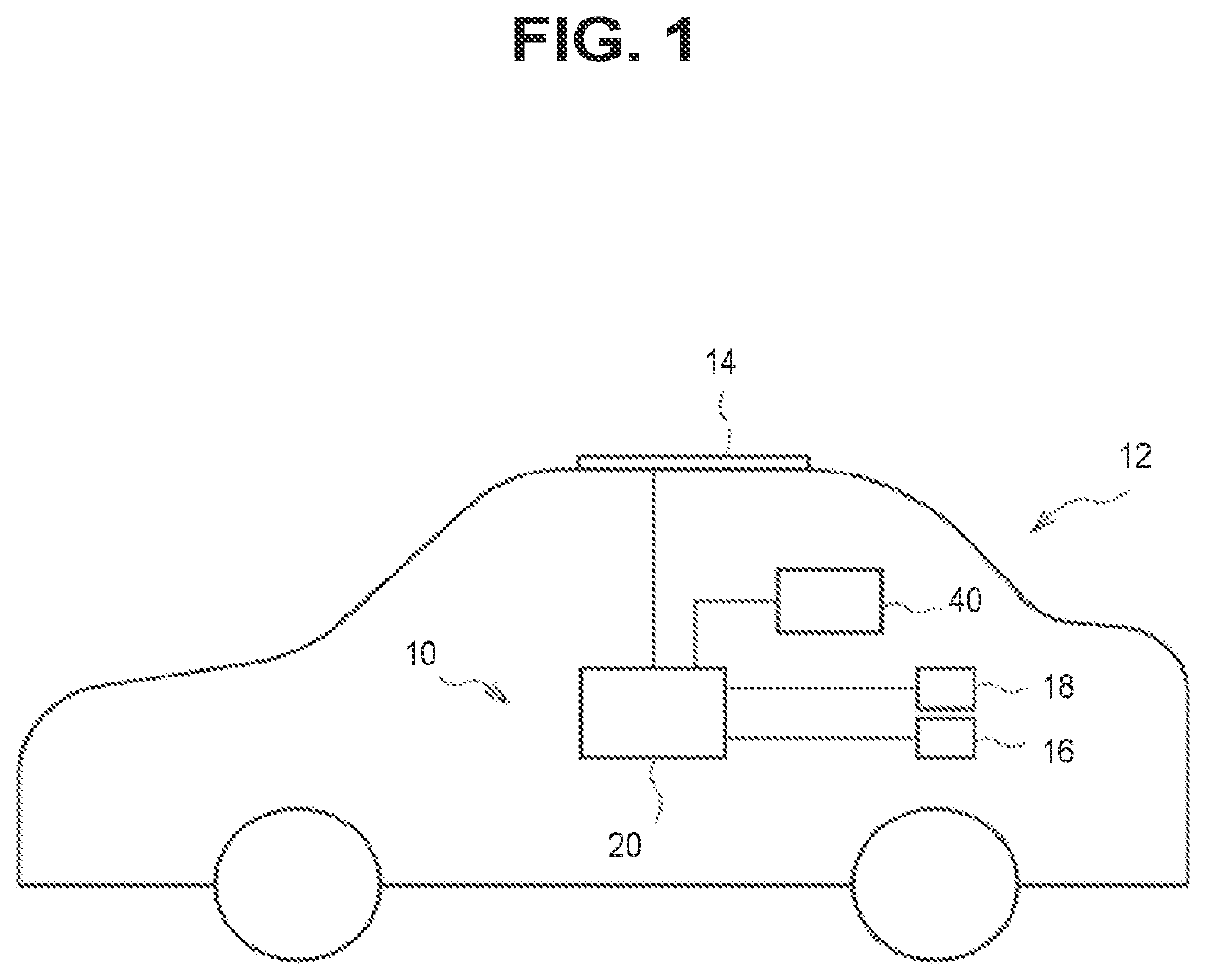
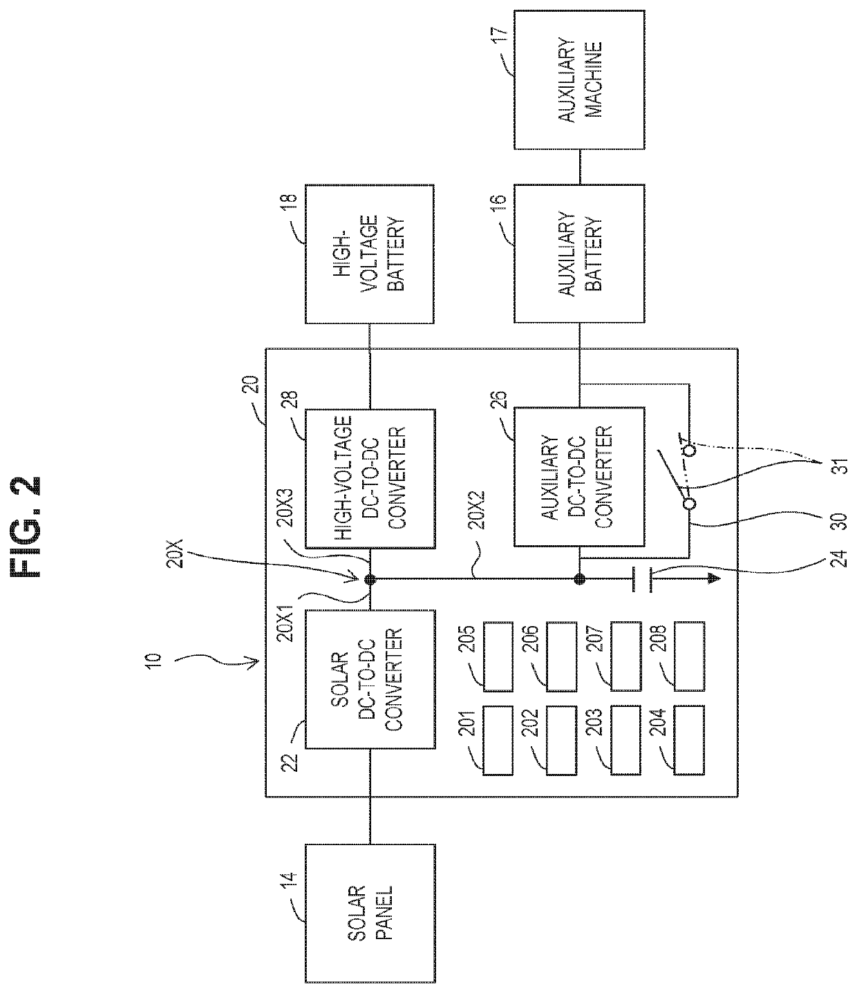
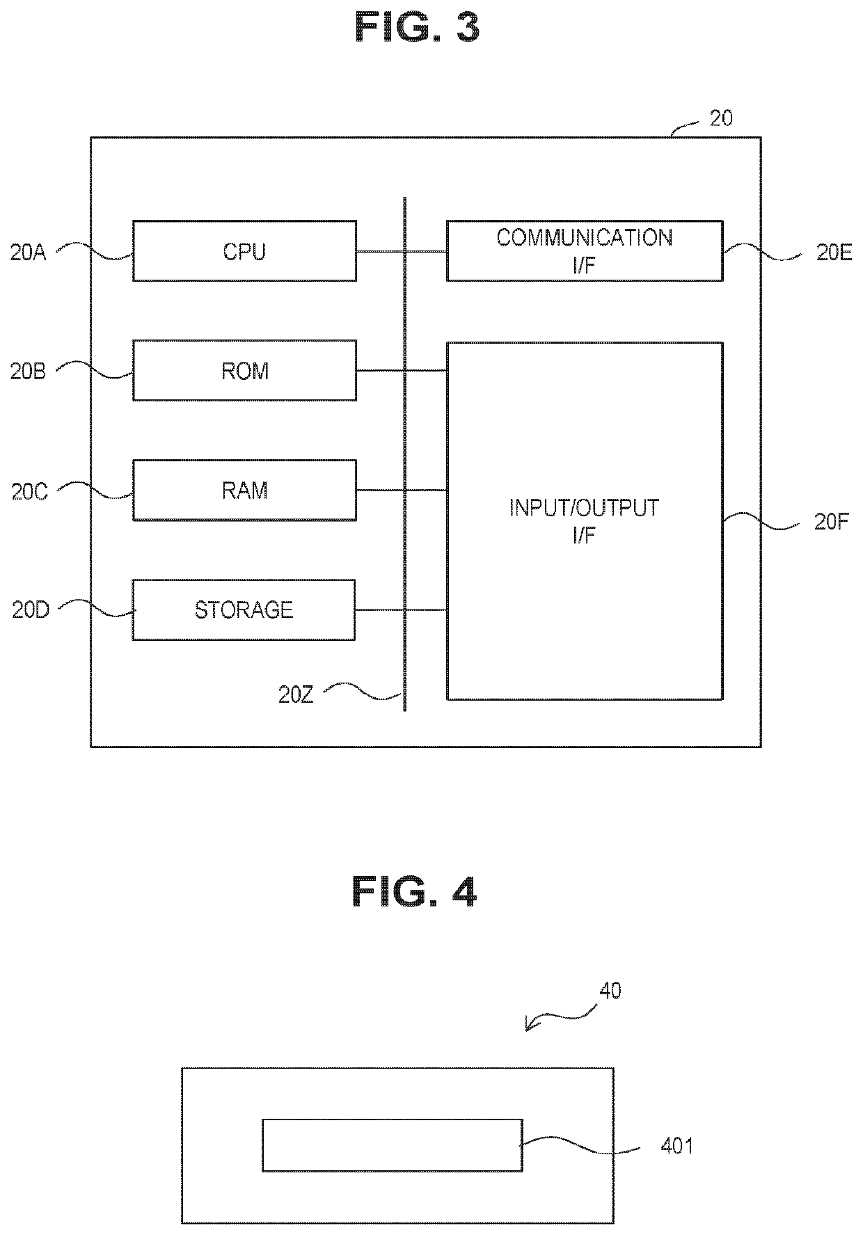
[0028]As shown in FIGS. 1 and 2, the system 10 is mounted on a vehicle 12. The system 10 includes a solar panel 14, an auxiliary battery (first battery) 16, an auxiliary machine 17, a high-voltage battery (second battery) 18, driving devices, a solar electronic control unit (ECU) 20, and a battery ECU 40.

[0029]The solar panel 14 mounted on a roof of the vehicle 12 is a power generation device that generates power by receiving sunlight. The solar panel 14 is a solar cell module which is an assembly of lots of solar cells. A power generation amount (kWh), an amount of power generated by the solar panel 14, and an output voltage have at least a correlation with an amount of solar radiation. The power generated by the solar pan...


PUM


Abstract

An in-vehicle solar charge control system includes a path switching unit provided in parallel with the first DC-to-DC converter on an electrical circuit that connects a solar DC-to-DC converter and a first battery and through which electricity having output power flows, and a switching unit controller which switches the path switching unit between a first state in which the output power is supplied to the first battery without being input to the first DC-to-DC converter, and a second state in which the output power is allowed to be input to the first DC-to-DC converter that is switched to the first operating state by a converter control unit.

Description

CROSS-REFERENCE TO RELATED APPLICATION[0001]This application claims priority to Japanese Patent Application No. 2021-022832 filed on Feb. 16, 2021, incorporated herein by reference in its entirety.BACKGROUND1. Technical Field[0002]The present disclosure relates to an in-vehicle solar charge control system, an in-vehicle solar charge control method, and a program.2. Description of Related Art[0003]Japanese Unexamined Patent Application Publication No. 2019-126219 discloses an in-vehicle solar charge control system that supplies power generated by a solar panel to a battery via two DC-to-DC converters.SUMMARY[0004]The electric power generated by the solar panel of the in-vehicle solar charge control system of JP 2019-126219 A is always supplied to the battery via two DC-to-DC converters. Consequently, the in-vehicle solar charge control system of JP 2019-126219 A loses a large amount of power due to the DC-to-DC converters.[0005]In consideration of such facts, the present disclosure i...

Claims


Application Information

Patent Timeline
IPC IPC(8): B60L8/00B60L53/20B60L53/62
CPCB60L8/003B60L53/20B60L58/20B60L2210/10B60L53/62B60L1/00B60L1/003B60L1/14H02J7/00712H02J7/0048H02J7/35Y02T10/7072
Inventor MIYAMOTO, YUMAOHKOSHI, KOHKITAKAHASHI, MASAHIROKAWAMURA, AKINORIHAYASHI, TAISUKEFUKAI, TAKASHI
Owner TOYOTA JIDOSHA KK
Why Eureka
Try Eureka