
Millimeter-wavelength network map for use in a beamforming procedure

a network map and millimeter wave technology, applied in the field of communication systems, can solve the problems of extremely high path loss and short range of communications using the mmw radio frequency band, and the number of possible beams that may need to be scanned during the beamforming procedure can be quite large, and achieve the effect of short range, high path loss and short rang

Active Publication Date: 2019-10-22
QUALCOMM INC
View PDF35 Cites 2 Cited by
  • Summary
  • Abstract
  • Description
  • Claims
  • Application Information

AI Technical Summary

Benefits of technology

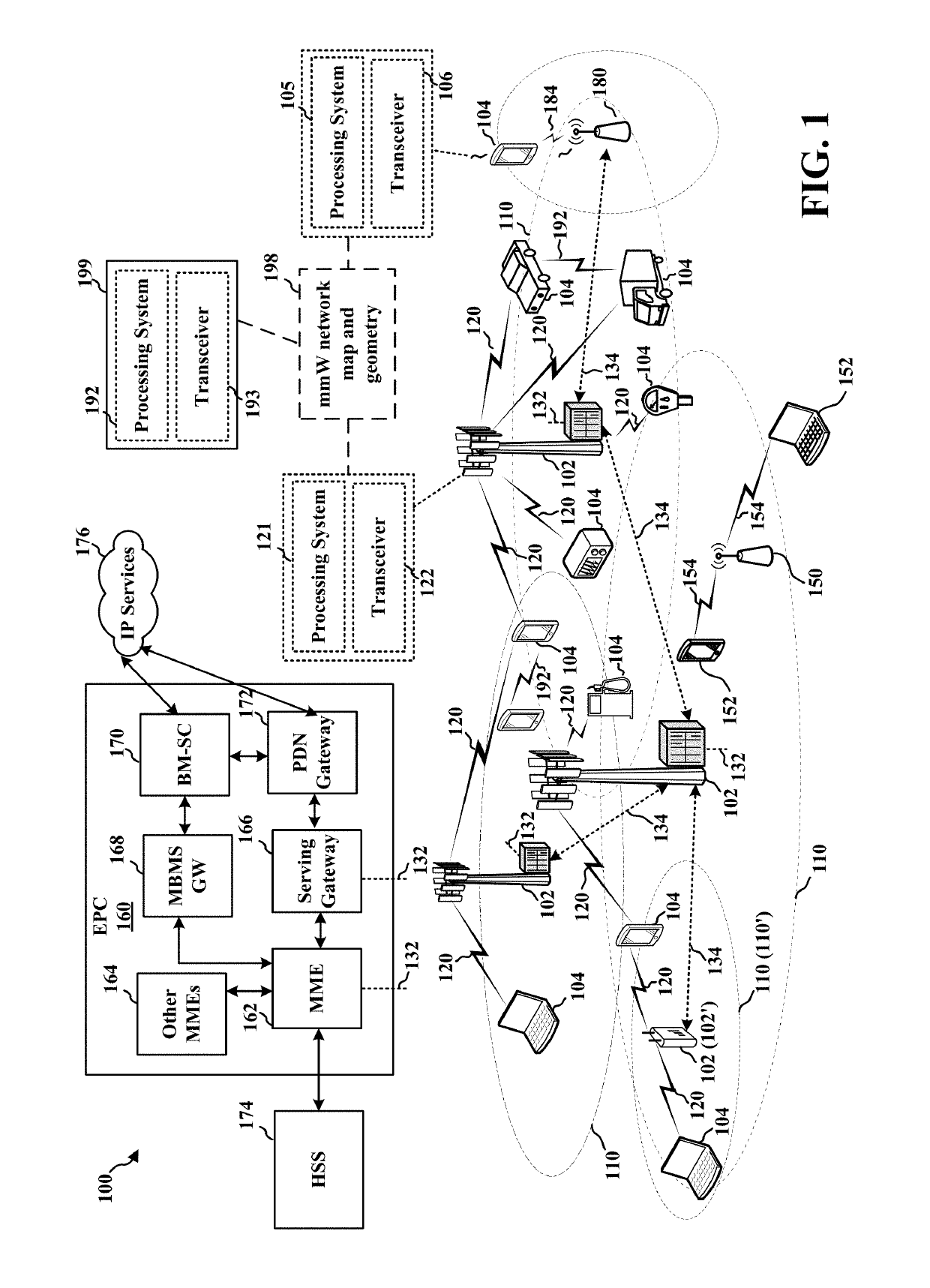
This patent text describes a method to improve the speed and efficiency of beamforming procedures in millimeter-wave (mmWave) wireless networks. It suggests using broader beams at the base station and a pseudo-omni beam at the user equipment (UE) to quickly scan for available beams and reduce the time needed for the beamforming process. However, this method may sacrifice some of the peak performance gain that can be achieved by scanning narrow beams. To address this, the patent proposes creating a map of mmWave cells or determining the geometry of mmWave cells to identify the most likely beams to use for communication between the base station and the UE. This approach helps improve the beamforming procedure while reducing latency and maintaining peak performance.

Problems solved by technology

However, communications using the mmW radio frequency band have extremely high path loss and a short range.
Communications using the mmW radio frequency band have extremely high path loss and a short range.
However, due to the potentially large number of antennas at an mmW base station and subarrays at a user equipment (UE), the number of possible beams that may need to be scanned during a beamforming procedure can be quite large.
A scanning process for a large number of potential beams may take an undesirable amount of time and create significant beam overhead.

Method used


Image

  • Millimeter-wavelength network map for use in a beamforming procedure
  • Millimeter-wavelength network map for use in a beamforming procedure
  • Millimeter-wavelength network map for use in a beamforming procedure

Examples


Embodiment Construction

[0066]The detailed description set forth below in connection with the appended drawings is intended as a description of various configurations and is not intended to represent the only configurations in which the concepts described herein may be practiced. The detailed description includes specific details for the purpose of providing a thorough understanding of various concepts. However, it will be apparent to those skilled in the art that these concepts may be practiced without these specific details. In some instances, well known structures and components are shown in block diagram form in order to avoid obscuring such concepts.

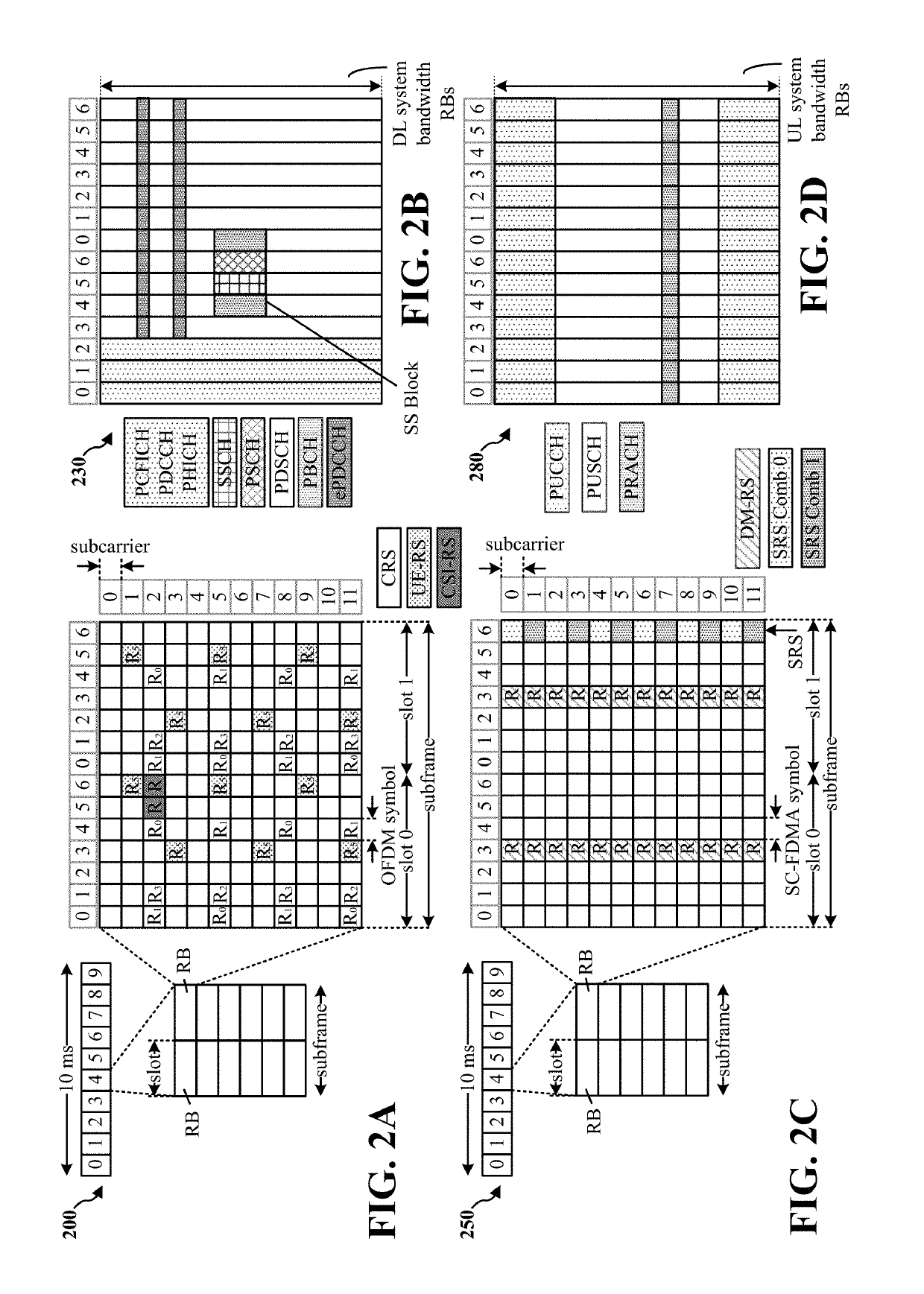
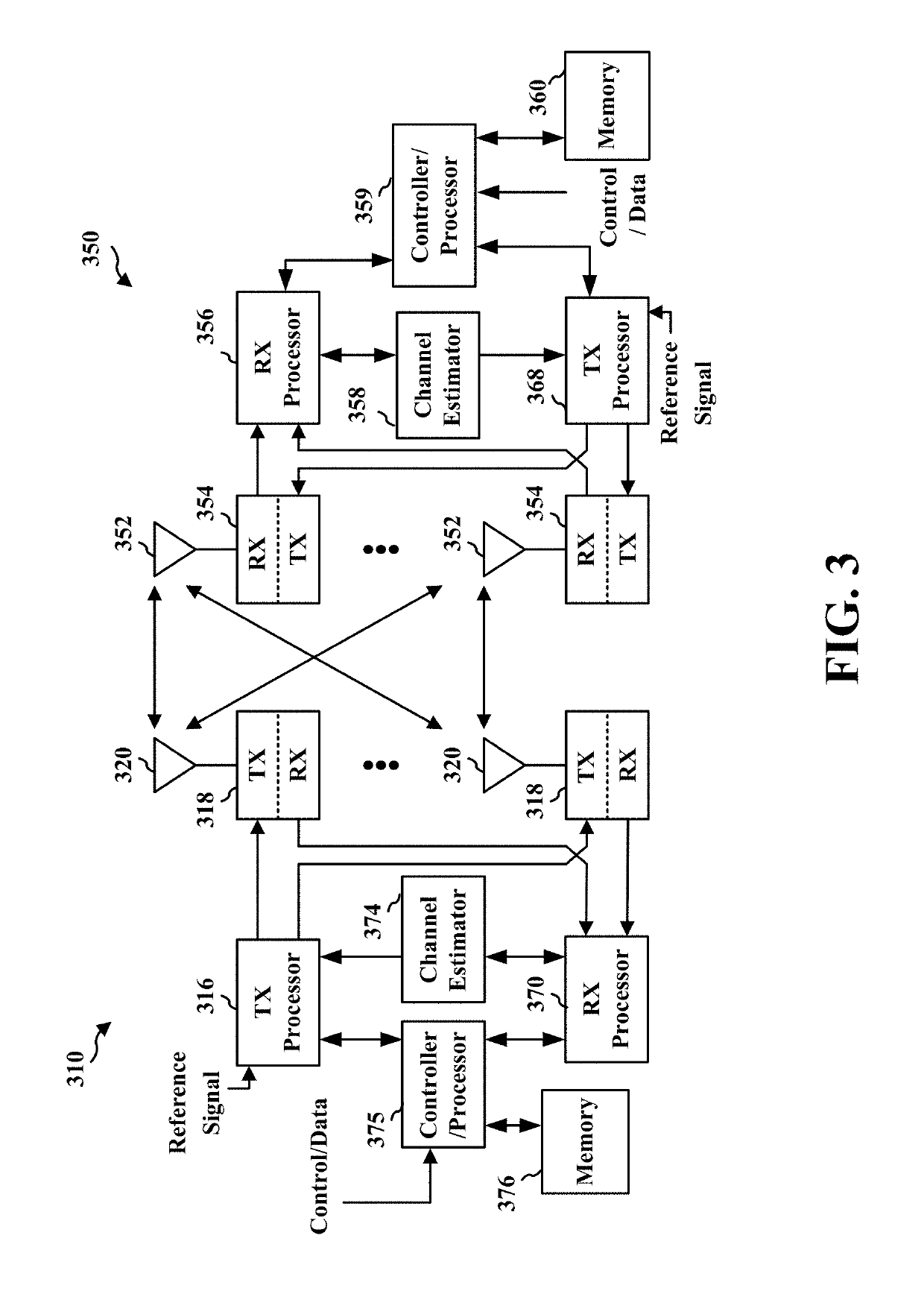
[0067]Several aspects of telecommunication systems will now be presented with reference to various apparatus and methods. These apparatus and methods will be described in the following detailed description and illustrated in the accompanying drawings by various blocks, components, circuits, processes, algorithms, etc. (collectively referred to as “elements...


PUM


Abstract

Aspects described herein may enable a network entity to create an mmW cell geometry and / or to seed a base station codebook and a UE codebook to improve a beamforming procedure while maintaining peak performance gain that is provided by scanning narrower beams. The network entity may provide information associated with the base station codebook and the UE codebook to the base station. The network entity may also provide, to the base station, a subframe structure to be used during a beamforming procedure that is based on the base station codebook and the UE codebook. The base station and the UE may perform the beamforming procedure based in the subframe structure using beam orientations indicated in the base station codebook and the UE codebook. From the beamforming procedure, the base station and the UE may determine an access beam to be used in communication between the base station and the UE.

Description

CROSS-REFERENCE TO RELATED APPLICATION(S)[0001]This application claims the benefit of U.S. Provisional Application Ser. No. 62 / 411,435, entitled “MILLIMETER-WAVELENGTH NETWORK MAP FOR USE IN A BEAMFORMING PROCEDURE” and filed on Oct. 21, 2016; U.S. Provisional Application Ser. No. 62 / 411,503, entitled “CROWDSOURCING MILLIMETER WAVE NETWORK GEOMETRY WITH A CLOUD-BASED SERVER” and filed on Oct. 21, 2016; U.S. Provisional Application Ser. No. 62 / 414,645, entitled “UE LOCALIZATION VIA MILLIMETER-WAVE NETWORK MAP” and filed on Oct. 28, 2016; and U.S. Provisional Application Ser. No. 62 / 414,642, entitled “MILLIMETER-WAVE NETWORK OPTIMIZATION A NETWORK MAP” and filed on Oct. 28, 2016. The disclosures of the preceding provisional applications are expressly incorporated by reference herein in its entirety.INTRODUCTION[0002]The present disclosure relates generally to communication systems, and more particularly, to a millimeter-wavelength (mmW) network map for use in a beamforming procedure.[...

Claims


Application Information

Patent Timeline
Patent Type & Authority Patents(United States)
IPC IPC(8): H04W64/00H04B7/08H04W4/02H04W4/50H04L25/03H04B7/0456H04B7/0452H04B7/0408H04B7/026H04B7/06H04W74/00H04W36/32H04W16/28H04W16/14H04W36/00
CPCH04W64/006H04W4/025H04B7/0697H04B7/0478H04B7/026H04W16/28H04W74/006H04W4/50H04B7/0663H04W4/023H04W36/32H04B7/0695H04L25/03898H04B7/0408H04B7/0639H04B7/063H04B7/0452H04B7/0834H04W16/14H04W36/0072H04W64/003H04W72/046H04L25/03904H04W64/00H04W36/322
Inventor RAGHAVAN, VASANTHANTOUBOUL, ASSAFLI, JUNYIFERNANDO, UDARA
Owner QUALCOMM INC
Learn More