Resonant fiber optical gyroscope using antiresonant nodeless fiber

a nodeless fiber, antiresonant technology, applied in the direction of optical elements, mechanical equipment, instruments, etc., can solve the problems of rfog affecting the accuracy or sensitivity of rfog, rfogs are susceptible to bias errors, and smaller rfogs typically have less accuracy than larger rfogs, so as to achieve the effect of minimizing gyroscope errors

Active Publication Date: 2019-10-22
HONEYWELL INT INC
View PDF27 Cites 5 Cited by
  • Summary
  • Abstract
  • Description
  • Claims
  • Application Information

AI Technical Summary

Benefits of technology

[0016]An optical resonator is provided. The optical resonator comprises: an optical resonator coil comprising a first port and a second port; wherein the optical resonator coil comprises antiresonant nodeless fiber; a resonator loop closure optics system; and wherein the antiresonant nodeless fiber has a length such that the resonant frequencies the optical resonator of the desired polarization state of light and of the undesired polarization state of light are separated by between a tenth of a free spectral range and nine tenths of a free spectral range to minimize gyroscope errors.

Problems solved by technology

In general, the size of the RFOG affects the accuracy or sensitivity of a RFOG.
For example, smaller RFOGs typically have less accuracy than larger RFOGs.
RFOGs are susceptible to bias error due to polarization cross-coupling.
These conditions result in polarization-induced bias error which can severely limit the accuracy of the RFOG because determination of the resonance centers for each of the resonant frequencies of the CW and CCW paths directly affects the rotational rate measurement.
In the RFOG, bias error is caused by the presence of glass material, through which light beams travel, in the optical fiber of the optical fiber coil.
This results in a non-reciprocal path length of the RFOG resonator, and an erroneous determined rate of rotation.
The glass material gives rise to other spurious effects, such as stimulated Brillouin scattering and a Faraday magneto-optical effect, which also cause bias error.
Although it eliminates the problematic core of glass material, hollow core bandgap fiber is not without its own problems.
Features within a hollow core bandgap fiber such as the nodes, or imperfections in launching into the hollow core bandgap fiber, cause light propagation in undesirable surface modes; light in surface modes travels in a collection of cells surrounding the core, rather than in the hollow core.
Surface modes can create bias error and noise due to back scattering of light in the surface modes and due to surface roughness, as well as multipath effects arising from cross-coupling between light in the surface modes and the core.

Method used


Image

  • Resonant fiber optical gyroscope using antiresonant nodeless fiber
  • Resonant fiber optical gyroscope using antiresonant nodeless fiber
  • Resonant fiber optical gyroscope using antiresonant nodeless fiber

Examples


example 2

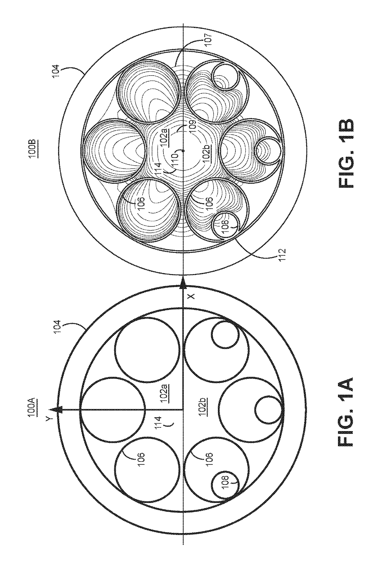
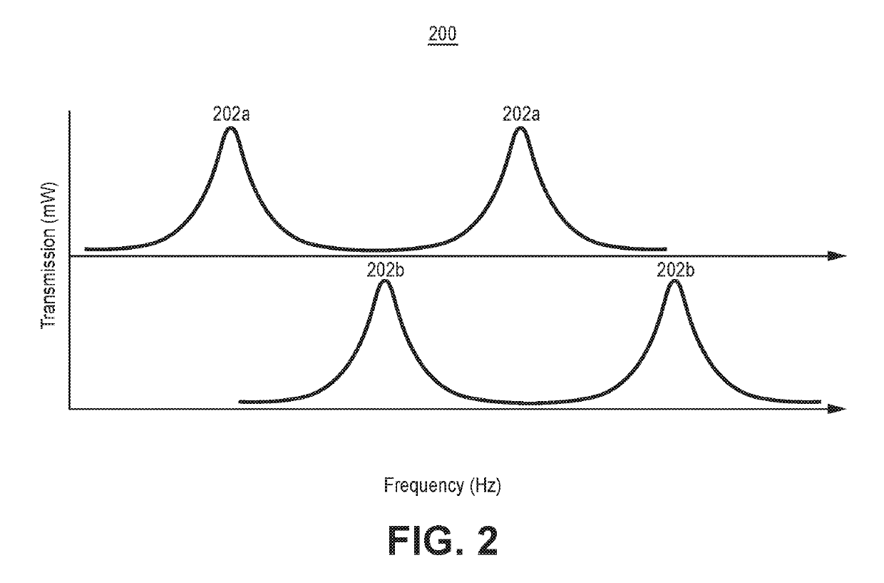
[0066 includes the optical resonator of Example 1, wherein the resonant frequencies the optical resonator of the desired polarization state of light and of the undesired polarization state of light are separated by at least one of (a) between a one quarter of a free spectral range and three quarters of a free spectral range, and (b) one half of a free spectral range.

example 3

[0067 includes the optical resonator of any of Examples 1-2, wherein the antiresonant nodeless fiber comprises at least one of antiresonant nodeless fiber which is nested and antiresonant nodeless fiber which is not nested.

example 4

[0068 includes the optical resonator of Example 3, wherein the antiresonant nodeless fiber comprises tubes, and wherein each tube has a cross section that is circular or elliptical.


PUM


Abstract

An optical resonator is provided. The optical resonator comprises: an optical resonator coil comprising a first port and a second port; wherein the optical resonator coil comprises antiresonant nodeless fiber; a resonator loop closure optics system; and wherein the antiresonant nodeless fiber has a length such that the resonant frequencies the optical resonator of the desired polarization state of light and of the undesired polarization state of light are separated by between a tenth of a free spectral range and nine tenths of a free spectral range to minimize gyroscope errors.

Description

CROSS-REFERENCE TO RELATED APPLICATIONS[0001]This application claims benefit of U.S. Provisional Application Ser. No. 62 / 613,918, filed Jan. 5, 2018, and titled “HOLLOW CORE RESONANT FIBER OPTICAL GYROSCOPE,” which is incorporated herein by reference in it entirety.STATEMENT REGARDING FEDERALLY SPONSORED RESEARCH OR DEVELOPMENT[0002]This invention was made with Government support under Government Contract Number Ordnance Technology Base Agreement No. 2016-316, Ordnance Agreement No. 1 and 2 awarded by DOTC. The Government has certain rights in this invention.BACKGROUND OF THE INVENTION[0003]Gyroscopes are used to measure rotation rates or changes in angular velocity about an axis. A resonant fiber optic gyroscope (RFOG) includes a light source, a beam generating device, and an optical fiber coil coupled to the beam generating device. The beam generating device transmits light beams into the coil that propagate in a clockwise (CW) direction and a counter-clockwise (CCW) direction alo...

Claims


Application Information

Patent Timeline
Patent Type & Authority Patents(United States)
IPC IPC(8): G01C19/72F21V8/00
CPCG01C19/722G01C19/727G02B6/0096G01C19/721G02B6/02328G02B6/02366
Inventor SANDERS, GLEN A.LASKOSKIE, CLARENCE EUGENENARAYANAN, CHELLAPPANSTRANDJORD, LEE K.
Owner HONEYWELL INT INC
Why Eureka
Try Eureka