
Method of analyzing a cable, based on an auto-adaptive correlation, for the detection of soft defects

Active Publication Date: 2019-10-08
COMMISSARIAT A LENERGIE ATOMIQUE ET AUX ENERGIES ALTERNATIVES
View PDF6 Cites 0 Cited by
  • Summary
  • Abstract
  • Description
  • Claims
  • Application Information

AI Technical Summary

Benefits of technology

The patent describes a method and device for analyzing a cable by injecting a reference signal and measuring the reflection of it in the cable. The method involves calculating the intercorrelation between the reference signal and the reflection measurement in a moving window of duration at least equal to 2T. The intercorrelation is then normalized by a factor dependent on the integration of the reflection measurement over the same window. The method can be used to detect faults in the cable by seeking an extremum of the normalized intercorrelation. The invention has the technical effect of providing a reliable and accurate method for analyzing cables, which can be used in various applications such as cable installation and maintenance.

Problems solved by technology

These cables are subject to the same stresses as the systems that they connect and may be subject to failures.
Discontinuities most often result from faults that modify the characteristic impedance of the cable locally, thereby creating a discontinuity in its linear parameters.
In contrast, a soft defect, for example resulting from a superficial degradation of the cladding, insulator or conductor of the cable, generates a low-amplitude peak in the reflected reflectometry signal and therefore one that is not easily detectable with conventional time-domain methods.
The detection and location of soft defects in cables is a substantial problem for the industrial world because a fault in general first appears as a superficial fault but may, with time, progress to become more severe.
However it has the two-fold drawback of being complex to implement in an on-board system and of causing problems with false detections due to the existence of cross terms in the aforementioned transform.
However, this method still has the drawback of substantial complexity with regard to implementation in portable pieces of equipment.

Method used


Image

  • Method of analyzing a cable, based on an auto-adaptive correlation, for the detection of soft defects
  • Method of analyzing a cable, based on an auto-adaptive correlation, for the detection of soft defects
  • Method of analyzing a cable, based on an auto-adaptive correlation, for the detection of soft defects

Examples


Embodiment Construction

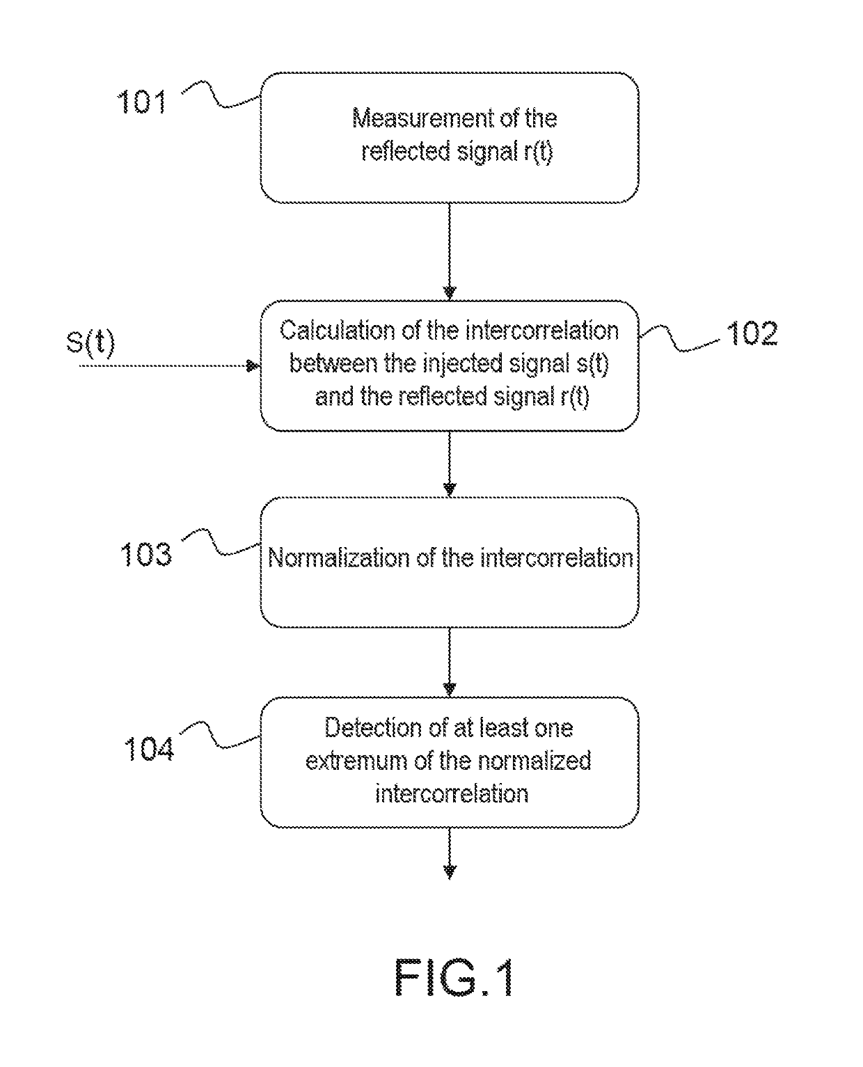
[0041]FIG. 1 shows the main steps implemented in the analyzing method according to the invention.

[0042]According to the well-known principle of reflectometry methods, a reference signal S(t) is injected at a point into the cable to be analyzed, this point possibly being one end of the cable or an injection point located anywhere on the cable.

[0043]In a first step 101 of the method according to the invention, the reflection r(t) of the injected signal is measured. This measurement may be made at the injection point or at another measurement point located anywhere on the cable. The reflected signal is measured over a given duration in particular set depending on the length of the cable and its physical characteristics (for example the propagation speed of the signal in the cable).

[0044]In a second step 102, the intercorrelation between the injected signal and the reflected signal is calculated. The intercorrelation is advantageously calculated over a duration at least equal to 2T wher...


PUM


Abstract

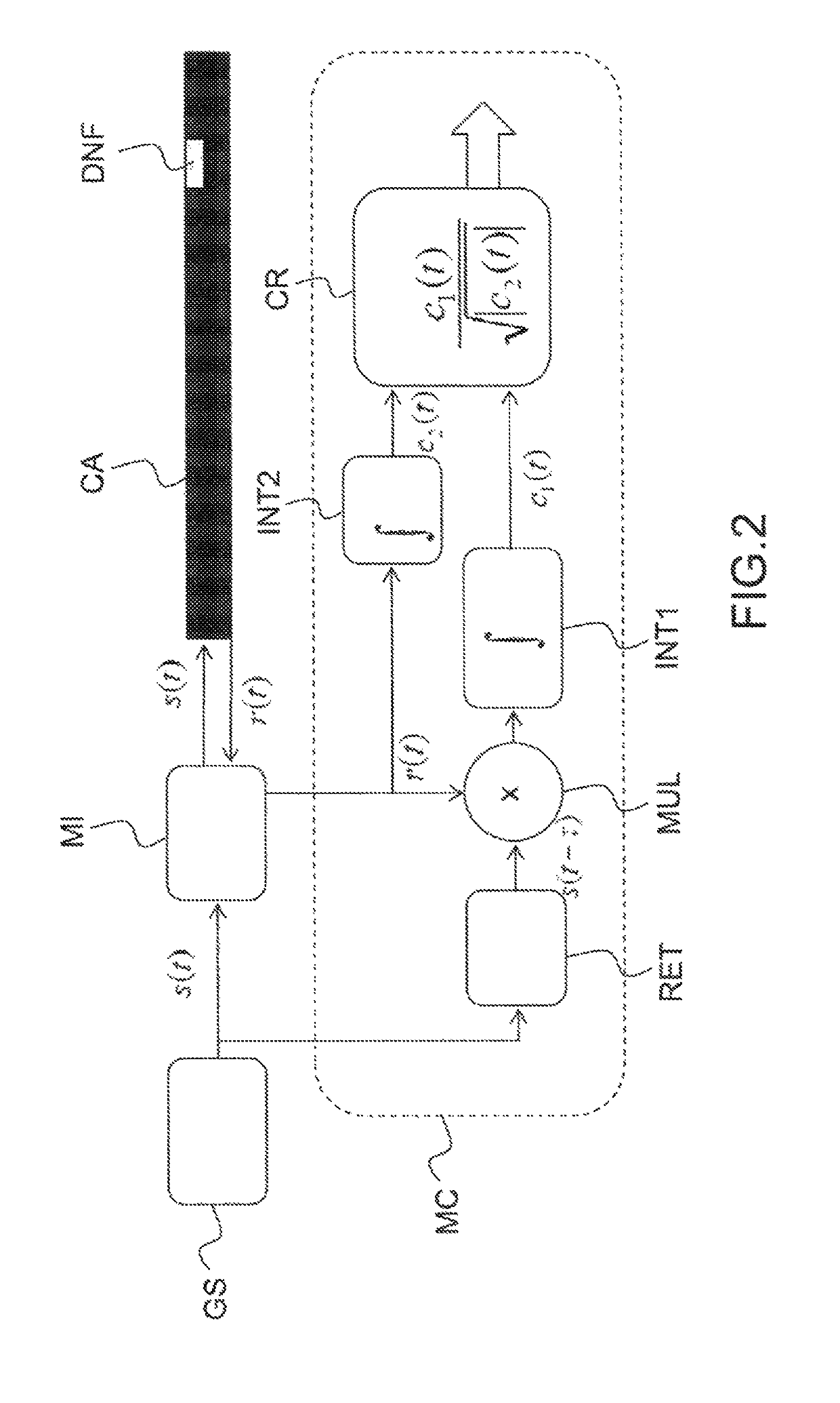
A method for analyzing a cable into which a reference signal s of time support limited to a duration T is injected comprises the following steps: calculating the intercorrelation, in a sliding window of duration D at least equal to 2T, between the injected reference signal s and a measurement r of the reflection of the reference signal s in the cable, normalizing the calculated intercorrelation by a factor dependent on the integration of the reflection measurement r over the same sliding window of duration D.

Description

CROSS-REFERENCE TO RELATED APPLICATIONS[0001]This application is a National Stage of International patent application PCT / EP2015 / 071606, filed on Sep. 21, 2015, which claims priority to foreign French patent application No. FR 1459402, filed on Oct. 2, 2014, the disclosures of which are incorporated by reference in their entirety.FIELD OF THE INVENTION[0002]The invention relates to a reflectometry method and system for detecting and locating soft defects in a cable. The field of the invention is that of wiring diagnostic systems based on the reflectometry principle.BACKGROUND[0003]Cables are omnipresent in all electrical systems, for the supply of power or transmission of information. These cables are subject to the same stresses as the systems that they connect and may be subject to failures. It is therefore necessary to be able to analyze their state and to return information on the detection of faults, but also on their location and their type, in order to help with maintenance. ...

Claims


Application Information

Patent Timeline
IPC IPC(8): G01R31/11
CPCG01R31/11
Inventor SALLEM, SOUMAYARAVOT, NICOLAS
Owner COMMISSARIAT A LENERGIE ATOMIQUE ET AUX ENERGIES ALTERNATIVES
Learn More