Thermally driven environmental control unit

a control unit and environmental technology, applied in the operation mode of machines, refrigeration machines, light and heating apparatus, etc., can solve the problems of high electrical demands to handle the pressurized parts of the system, limited adsorption systems, and significant amounts of energy required to effectively change the temperature of the space, etc., to achieve efficient overall heating or cooling systems, simple environmental control units, and easy separation for re-use

Inactive Publication Date: 2019-10-08
APPLIED RES ASSOCS INC
View PDF41 Cites 0 Cited by
  • Summary
  • Abstract
  • Description
  • Claims
  • Application Information

AI Technical Summary

Benefits of technology

[0010]The design of the system may vary based upon whether the system is intended to heat or cool an environment, or both; however, the simplicity of the design and the lack of a pressurized loop allow for simple environmental control units, and efficient overall heating or cooling systems. Integral to the design of the system is the selection of the solute and the solvent, which should be selected (1) to generate an effective enthalpy change in solution through the mixing process, and (2) with different boiling points, so that the solvent and solute may be easily separated for re-use.

Problems solved by technology

These systems tend to be large and bulky, and require many hydraulic loops and auxiliary components, resulting in systems that require significant amounts of energy to effectively change the temperature of a space.
The system requires multiple auxiliary components to handle its hydraulic design, and high electrical demands to handle the pressurized portions of the system.
Adsorption systems are limited, however, due to the weak mass and heat transfer characteristics of the adsorbent beds.
Specifically, the adsorbents, such as activated carbon, zeolite or silica gel, have low thermal conductivities and poor porosity characteristics.
Consequently, the system typically has a bulky collector / generator / adsorber component which requires excessive heating capacity, leading to a rather low thermal coefficient of performance (COP).
These systems can be satisfactorily operated at generator temperatures as low as 65° C. However, similar to the absorption system, they require many hydraulic loops and high auxiliary electricity loads.

Method used


Image

  • Thermally driven environmental control unit
  • Thermally driven environmental control unit

Examples


Embodiment Construction

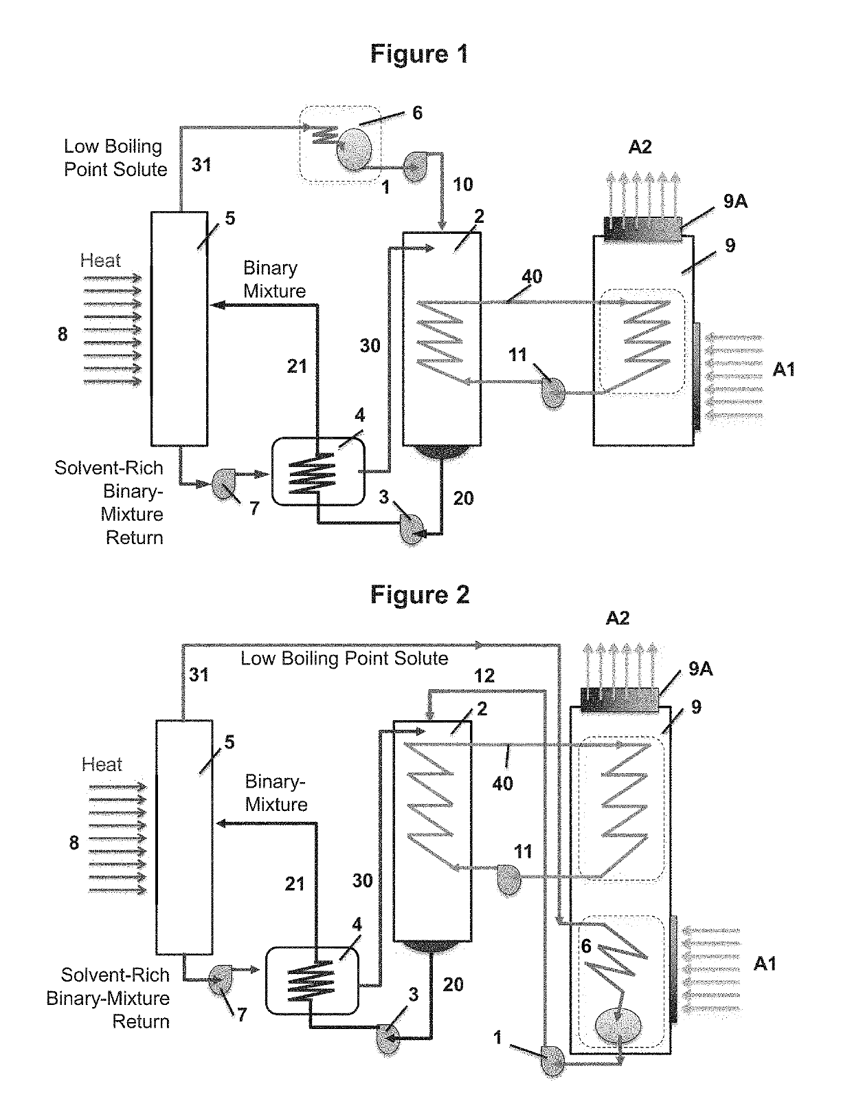
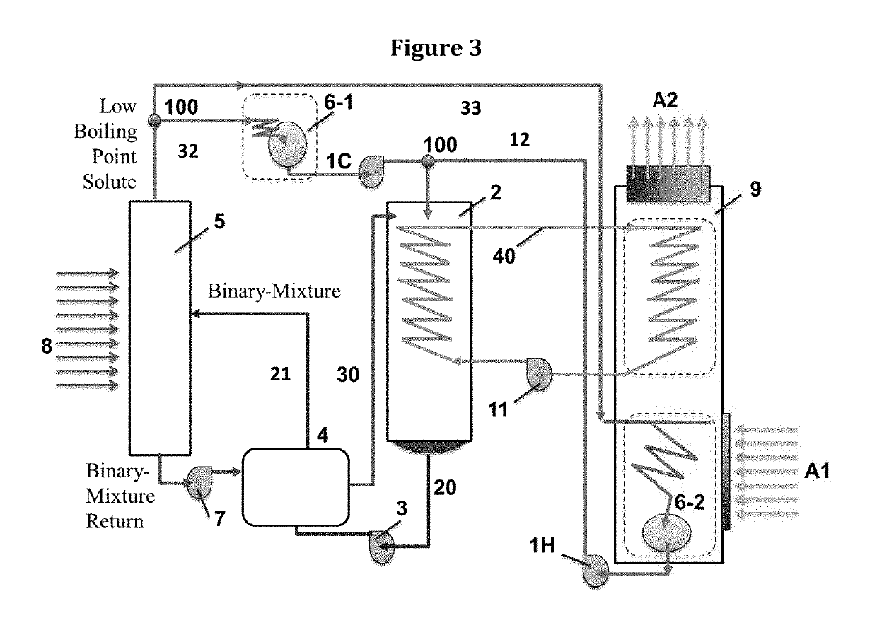
[0015]In one embodiment of the invention of the present system (shown in FIG. 1) the system is designed to provide cooling to an environment, in another embodiment of the invention (shown in FIG. 2) the system is designed to provide heating to an environment, and in a third embodiment of the invention (shown in FIG. 3) the system is designed to selectively provide cooling or heating to an environment.

[0016]As hereinabove described and shown in FIGS. 1, 2 and 3, the system of the present invention generally includes, in a closed loop, non-pressurized flow cycle, a mixing heat exchanger 2, a heat recovery unit 4, a fractionator / evaporator column 5 for separating the solute and the solvent, such as a fractionator, and a condenser 6. A liquid loop 40 is coupled with both the mixing heat exchanger 2 and an air handler 9, to provide warm or cool supply air. When the system is used to heat an environment, the condenser 6 is incorporated within the air handler 9; when the system is used for...


PUM


Abstract

The present invention regards a thermally driven, environmental control unit including, in a closed fluid-flow, non-pressurized circuit, a mixing heat exchanger, a heat recovery unit, a fractionator / evaporator, and one or more condensers. The system is designed to include at least one solute and a solvent, selected so that the mixture of each solute and the solvent produce an enthalpy change of between about 5 to 30 kJ / mol for cooling and −10 to −200 kJ / mol for heating. A plurality of pumps are integrated into the system to move the solute and the solvent, and a mixture thereof, among the various components of the present invention. The unit further includes a liquid loop coupled with the mixing heat exchanger and an air handler to provide warm or cool supply air. The present invention further regards a process for cooling or heating air using enthalpy change of solution associated with the dissolution of a solute in a solvent, at relatively constant atmospheric pressure, and separation of the solute from the solvent for re-use in the process.

Description

BACKGROUND OF THE INVENTION[0001]The present invention regards a system and a process for efficient cooling and / or heating that is capable of using multiple sources of thermal energy, including waste heat, renewable thermal energy, and fuel combustion. The process produces cooling by mixing a solute with a solvent that produces a positive enthalpy change, and produces heating by mixing a solute with a solvent that produces a negative enthalpy change. In both cases, the solute is then separated from the solvent using thermal energy, and the cooling / heating process is repeated in a continuous fashion.[0002]Thermally driven cooling and heating systems presently available on the market include absorption, adsorption, and ejector-compressor systems. These systems tend to be large and bulky, and require many hydraulic loops and auxiliary components, resulting in systems that require significant amounts of energy to effectively change the temperature of a space.[0003]For example, a simple ...

Claims


Application Information

Patent Timeline
Patent Type & Authority Patents(United States)
IPC IPC(8): F25B15/02F25B27/02
CPCF25B15/02Y02B30/62F25B27/02Y02A30/277Y02A30/274Y02A30/27
Inventor ZHOU, GONGSHAABAN, ALY H
Owner APPLIED RES ASSOCS INC
Why Eureka
Try Eureka