Substrate holding device, lithography apparatus, and article production method
a technology of holding device and substrate, which is applied in the direction of microlithography exposure apparatus, photomechanical treatment, instruments, etc., can solve the problem of weakening of the attracting for
- Summary
- Abstract
- Description
- Claims
- Application Information
AI Technical Summary
Benefits of technology
Problems solved by technology
Method used
Image

Examples
first embodiment
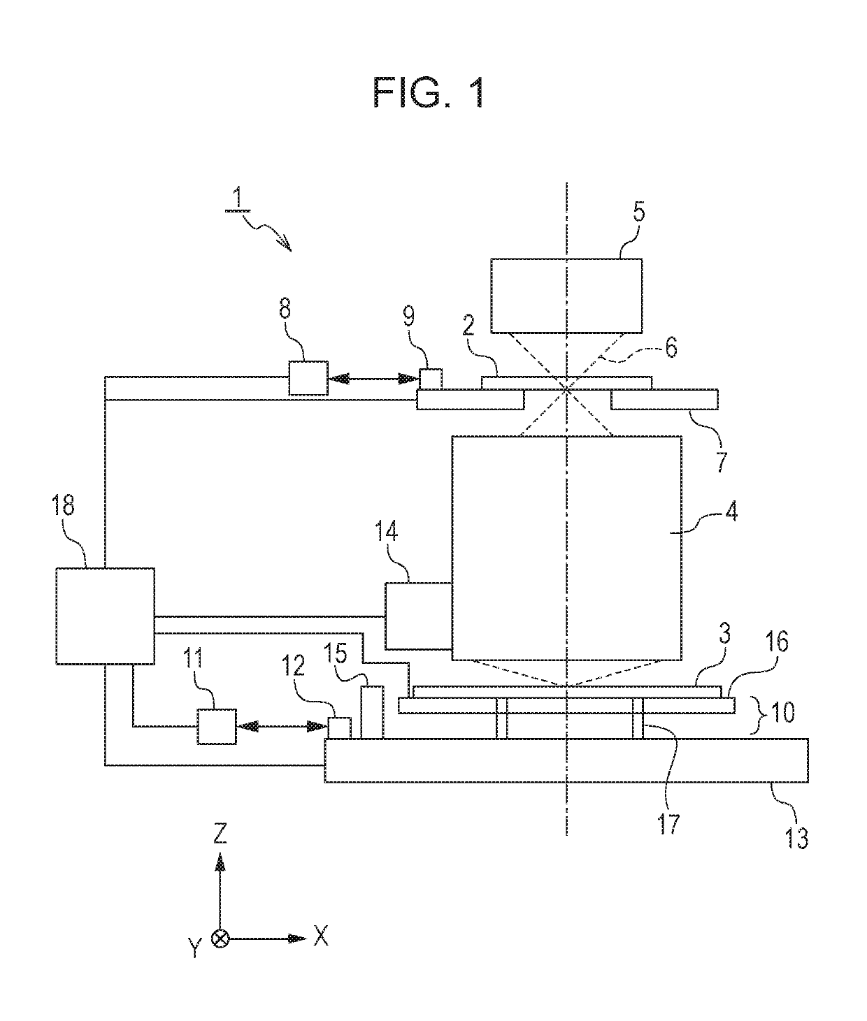
[0019]The configuration of an exposure apparatus 1 according to a first embodiment will be described with reference to FIG. 1. The exposure apparatus 1 is a projection exposure apparatus that transfers a pattern (for example, a circuit pattern) formed on a reticle 2 onto a substrate 3 by applying the i-line (wavelength 365 nm) while scanning the reticle 2 and the substrate 3 by a step-and-repeat method. In FIG. 1, the axis parallel to the optical axis of a projection optical system 4 (the vertical direction in the embodiment) is referred to as a Z-axis. In a plane perpendicular to the Z-axis, the direction in which the reticle 2 is scanned during exposure is referred to as an X-axis, and a non-scanning direction orthogonal to the X-axis is referred to as a Y-axis.
[0020]Illumination light (beam) 6 shaped by an illumination optical system 5 is applied onto the substrate 3 via the reticle 2 and the projection optical system 4. The substrate 3 is, for example, a single-crystal silicon s...
example
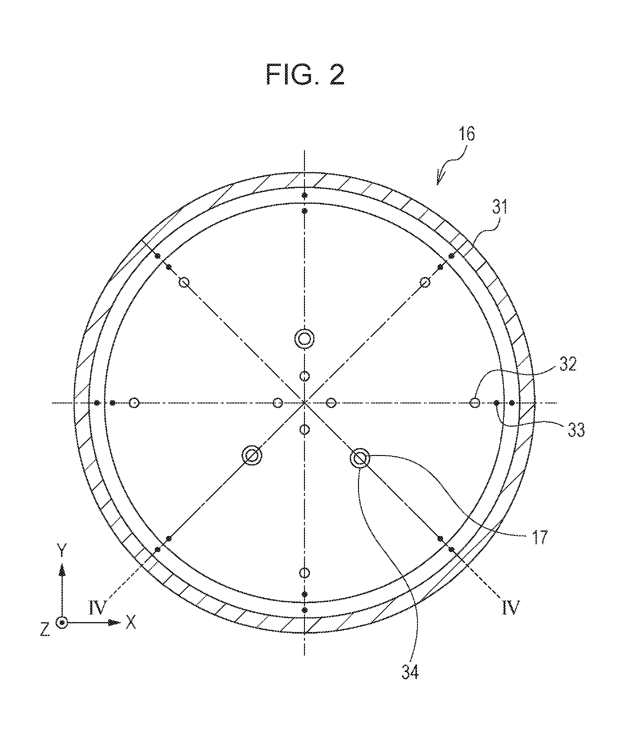
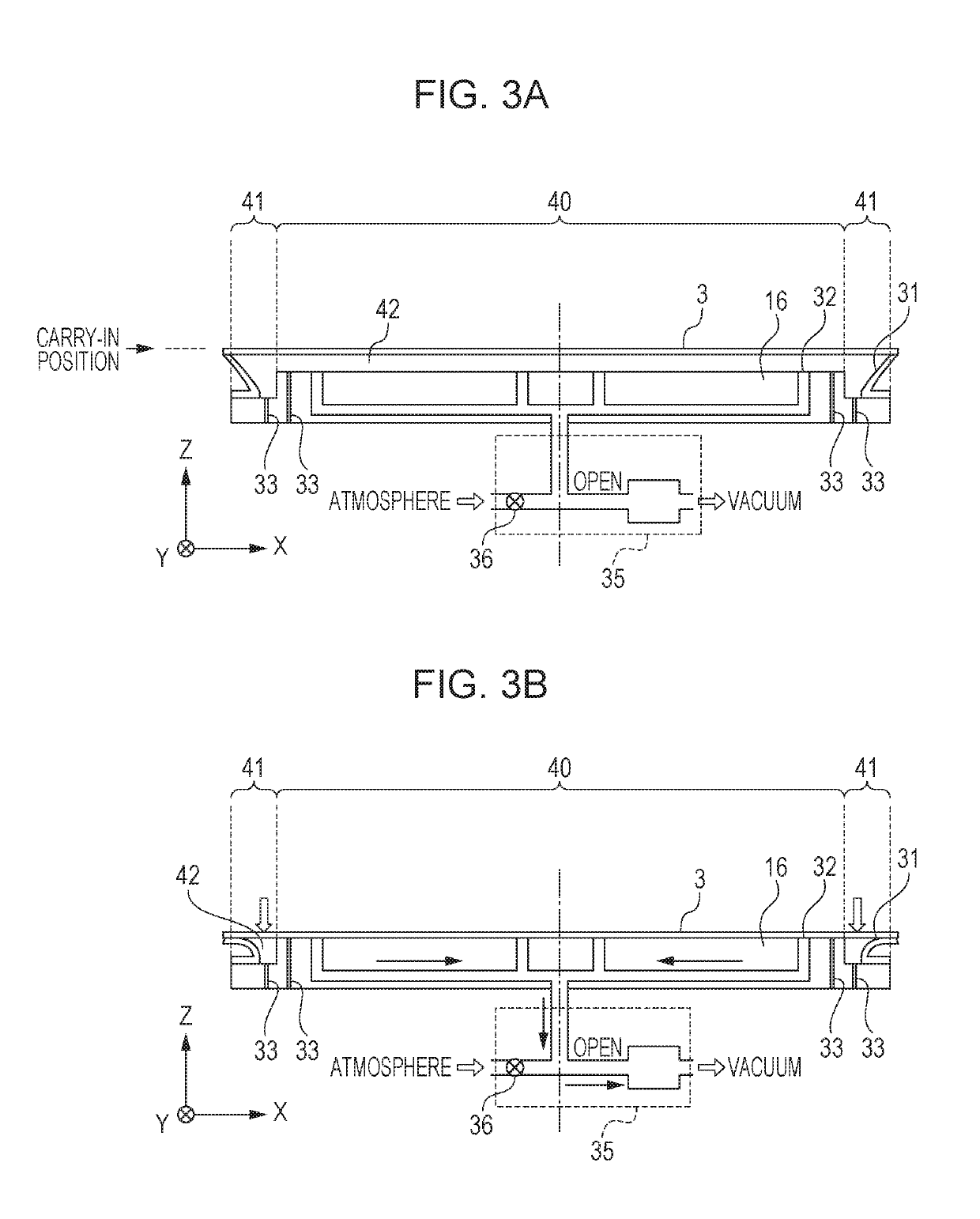
[0050]An example of the first embodiment will be described. In this example, a substrate 3 having a diameter of 300 mm was used. As the chuck 16, a chuck having open holes 33 and a chuck having no open holes 33 were prepared. In the chuck 16 having the open holes 33, the open holes 33 were formed to have a diameter of 0.3 mm so that the total cross-sectional area became 1.5 mm2.
[0051]A carry-out operation was repeated while changing the descending speed of the chuck 16 after the substrate 3 came into contact with the pins 17, and the descending speed at which displacement of the substrate 3 occurred was compared. The descending speed of the chuck 16 until the substrate 3 was delivered from the center part 40 to the pins 17 was common to both the chucks.
[0052]As result, in the chuck having no open holes 33, displacement of the substrate 3 was confirmed when the descending speed of the chuck was 0.2 mm / s or more at the time of delivering to the pins 17. In contrast, in the chuck 16 ha...
second embodiment
[0054]FIG. 5 is a cross-sectional view of a chuck 16 according to a second embodiment. Open holes 43 are provided at a position (a lead-in area of a seal member) 44, which is closed by a lip seal 31 led into a space 42 when a substrate 3 is attracted, of a substrate opposing surface in an outer peripheral part. This provides an effect of reducing leakage from the open holes 43 during attraction of the substrate 3.
[0055]In a carry-out operation, since the lip seal 31 returns to its original shape and the open holes 43 are opened, the atmosphere can be supplied into the space 42. Thus, it is possible to achieve both the effect of suppressing leakage when the substrate 3 is attracted and the effect of shortening the time taken to carry out the substrate 3.
PUM
| Property | Measurement | Unit |
|---|---|---|
| wavelength | aaaaa | aaaaa |
| diameter | aaaaa | aaaaa |
| diameter | aaaaa | aaaaa |
Abstract
Description
Claims
Application Information
 - R&D
- Intellectual Property
- Life Sciences
- Materials
- Tech Scout
- Unparalleled Data Quality
- Higher Quality Content
- 60% Fewer Hallucinations
Browse by: Latest US Patents, China's latest patents, Technical Efficacy Thesaurus, Application Domain, Technology Topic, Popular Technical Reports.
© 2025 PatSnap. All rights reserved.Legal|Privacy policy|Modern Slavery Act Transparency Statement|Sitemap|About US| Contact US: help@patsnap.com