Heat generator

a heat generator and generator technology, applied in the field of heat generators, can solve the problems of unsuitable for small domestic heat generation systems, achieve the effects of reducing energy consumption, reducing energy consumption, and reducing energy consumption

Active Publication Date: 2019-09-24
ROTAHEAT
View PDF28 Cites 5 Cited by
  • Summary
  • Abstract
  • Description
  • Claims
  • Application Information

AI Technical Summary

Benefits of technology

[0012]For cost effectiveness, the first disc with the runner vanes may be cast or machined from aluminium or aluminium alloy, other highly conducting materials such as copper or copper alloys could be used, but their costs are significantly higher. The second disc can be of steel or cast iron; but, for lightness, aluminium or aluminium alloy would be preferred.
[0031]In a further arrangement the hydraulic motor and rotary heat generator are mounted in a water tank to be heated for storage and supply source of hot water for a building or other facility; in this way transmission losses are minimised. In this embodiment it is possible to redesign the heater such that the magnets are covered and the second disc(s) are mounted on the shaft and the first disc is fixed, optionally too the runner vanes can be omitted so that fluid passes freely over the first disc which is heated but rotation of the second disc: this embodiment is less efficient than the first embodiment if the body of the device were immersed in water it may be a practical option.

Problems solved by technology

In practice it has been found that heat generators as described in WO2011 / 158030 are heavy, requiring large diameter wind turbines to be effective and are unsuitable for smaller domestic heat generation systems.
Furthermore there is a need for small hand operated heat generation systems for use in remote places or in emergency, where transport of a mast or availability of mast on which to mount a wind turbine to drive the heat generator is not practicable.

Method used


Image

  • Heat generator
  • Heat generator
  • Heat generator

Examples


Embodiment Construction

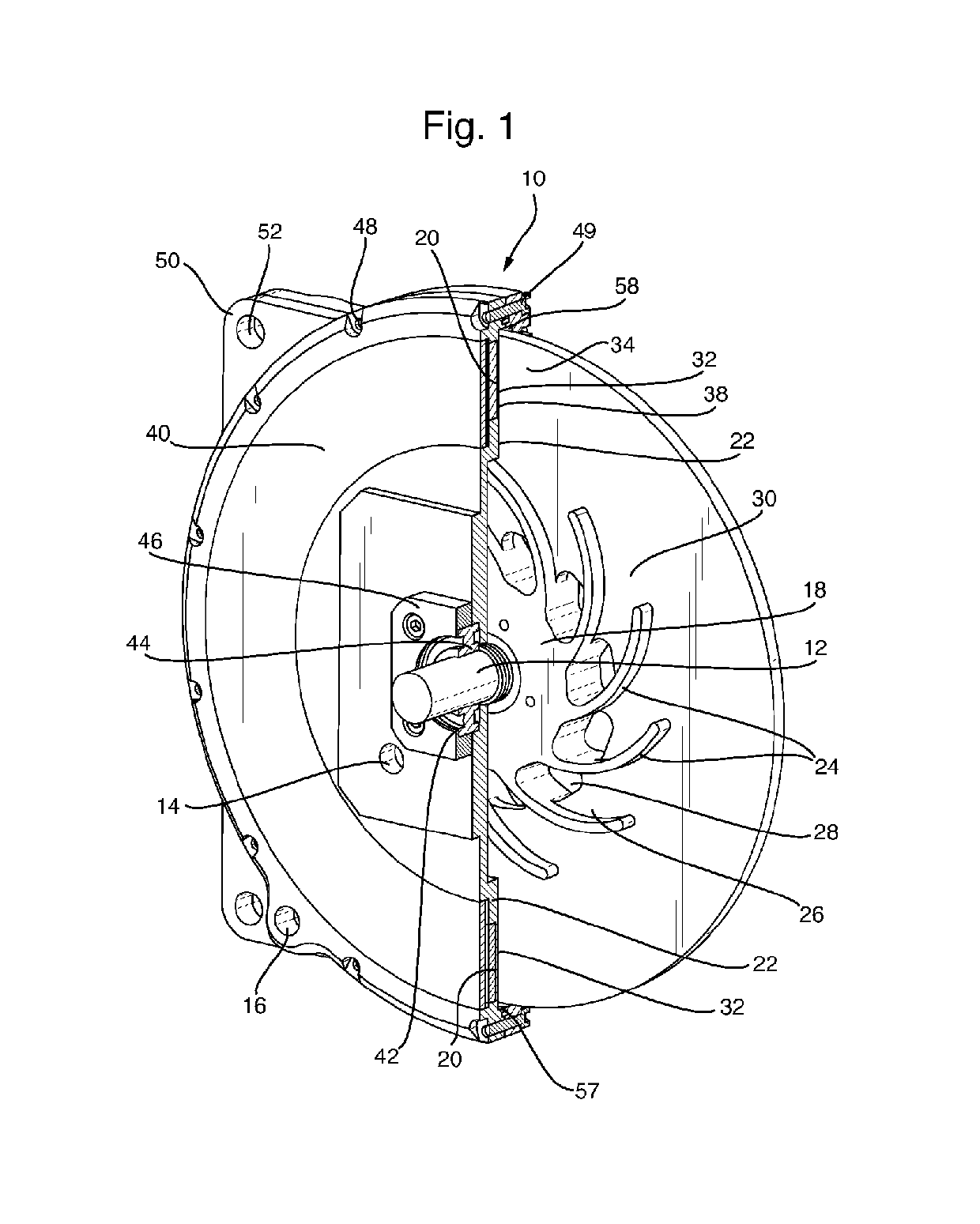
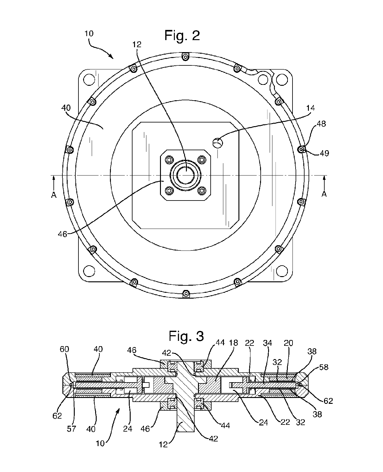
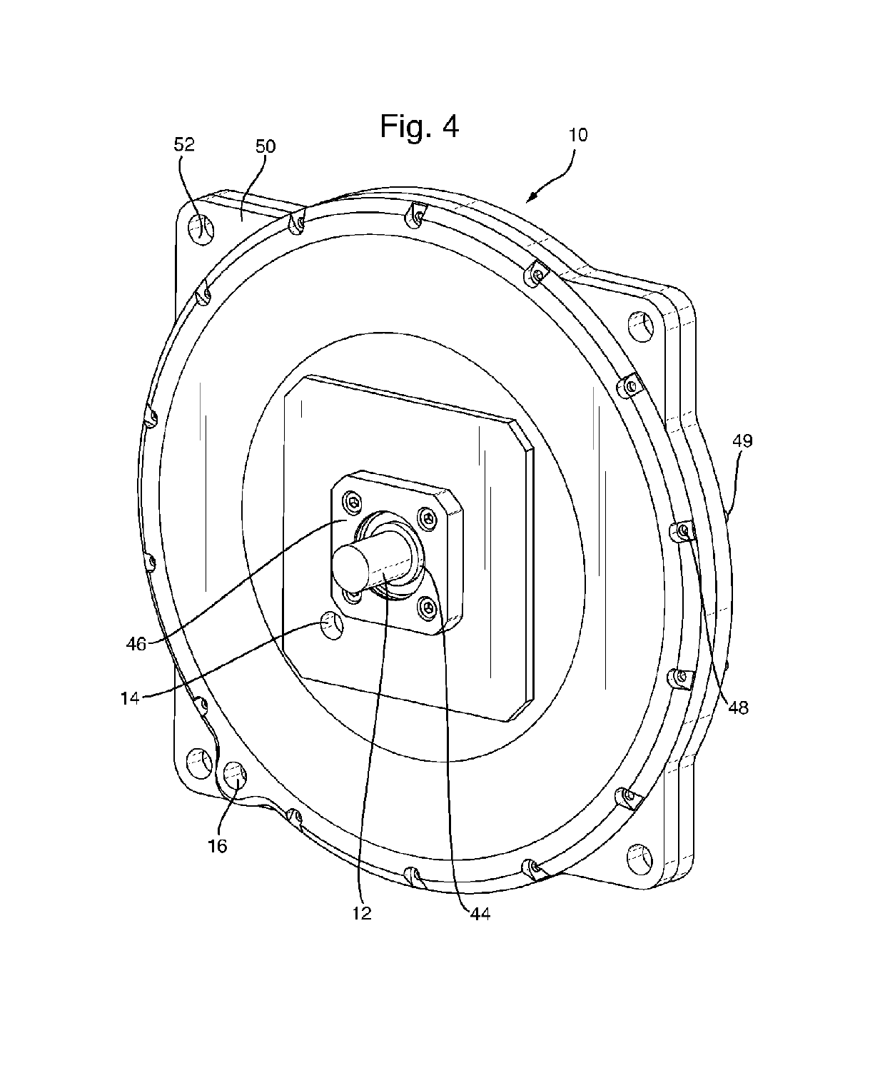
[0047]In FIGS. 1 to 6 a heat generator 10 comprises a shaft 12 (only partially shown) connected to a source of power, a fluid input 14 and fluid output 16. A first disc 18 comprising aluminium is mounted rigidly on the shaft 12. A plurality of magnets 20 parallel to the plane of the first disc 18 are mounted either side of it. A pair of second fixed discs 22 are mounted around the shaft but not coupled to it, close to and either side of the first disc 18; the planes of the second discs 22 are parallel to the first disc 18. A plurality of runner vanes are 24 cast as part of the first disc 18, upstanding up from the surface of the first disc on both sides thereof and forming a plurality paths 26 between the first and second discs 18 and 22 from close to the shaft 12 towards the magnets 20. The magnets are aligned with their NS axis lying radially to the pairs of second discs with one pole, say S, pointing to the centre of the second disc. The widths of said paths 26 increase from thei...


PUM


Abstract

A heat generator comprises a fluid input and fluid output, an electrically conducting disc mounted on a shaft, a plurality of magnets with their N-S axis aligned parallel to the plane of the first disc are mounted either side of the disc, a plurality of runner vanes upstanding from the disc and forming a plurality of widening fluid paths towards the magnets and allow fluid to flow over a vane free portion of the disc to exit the heat generator though the output. Drive systems are described in which high pressure fluid from a hydraulic motor connected to a turbine or Archimedean screw is used to drive the disc.

Description

[0001]This application is the U.S. national phase of International Application No. PCT / GB2014 / 052531 filed 18 Aug. 2014, which designated the U.S. and claims priority to GB Patent Application No. 1315019.8 filed 22 Aug. 2013, GB Patent Application No. 1321540.5 filed 6 Dec. 2013, and GB Patent Application No. 1407978.4 filed 6 May 2014, the entire contents of each of which are hereby incorporated by reference.TECHNICAL FIELD[0002]This invention relates to a heat generator.BACKGROUND ART[0003]PTL 0001: WO WO 2011 / 158030 A (CARBON ZERO LIMITED). 2011-06-15.[0004]describes a heat generator comprising a magnetic field that is both rotatable about a shaft and intersects a heat exchanger that characterised in that the heat exchanger comprises a flat first disc that is both electrically conducting and is disposed around the shaft, but not attached thereto, said first disc having a fluid path in the plane of the disc wherein heat generated in the first disc by induction as a result of rotat...

Claims


Application Information

Patent Timeline
Patent Type & Authority Patents(United States)
IPC IPC(8): H05B6/10
CPCH05B6/108H05B6/109Y02B10/30
Inventor NANGLE, DOUGLASTULLOCH, ANDREW
Owner ROTAHEAT
Why Eureka
Try Eureka