
Method and device for controlling an internal combustion engine

a technology of internal combustion engine and control device, which is applied in the direction of electric control, machines/engines, mechanical equipment, etc., can solve the problems of increasing the complexity affecting the efficiency of exhaust gas treatment, and unable to ensure the treatment of exhaust gas in the case, so as to increase the enthalpy of exhaust gas

Active Publication Date: 2019-09-24
ROBERT BOSCH GMBH
View PDF6 Cites 0 Cited by
  • Summary
  • Abstract
  • Description
  • Claims
  • Application Information

AI Technical Summary

Benefits of technology

The present invention relates to a method for injecting gaseous fuel directly into an internal combustion engine to heat a catalytic converter and reduce emissions during a cold start. The method allows for rapid and effective heating of the catalytic converter, resulting in significant reduction of emissions during a cold start. The method also provides smoother running of the engine, especially during idling operation. The method includes a main injection of gaseous fuel followed by a first post-injection and a second post-injection. The second post-injection takes place after the ignition and is smaller in fuel quantity than the main injection. The second post-injection helps to increase the exhaust-gas temperature and reduce emissions. The method can be carried out as a lean process using a lambda value of approximately 1.05 to minimize raw NOx emissions. The method can still be used even if gas pressure is reduced, such as due to a low gas tank level.

Problems solved by technology

An issue with gaseous fuels, especially natural gas, in comparison with gasoline or other liquid fuels is an exhaust-gas treatment.
In particular if the gaseous fuel has methane (CH4) as the main component, an exhaust-gas treatment becomes more complex than in the case or longer-chained hydrocarbons of liquid fuels.
A sufficient exhaust-gas treatment cannot be ensured in the case of cold catalytic converters, in particular.
Of course, attention should be paid to keep the raw emissions of uncombusted hydrocarbons and particles as low as possible because they would otherwise clearly worsen the emission behavior in a catalytic converter that is still not functioning due to insufficient temperatures.
This allows for a particularly uncomplicated control of the method.

Method used


Image

  • Method and device for controlling an internal combustion engine

Examples


Embodiment Construction

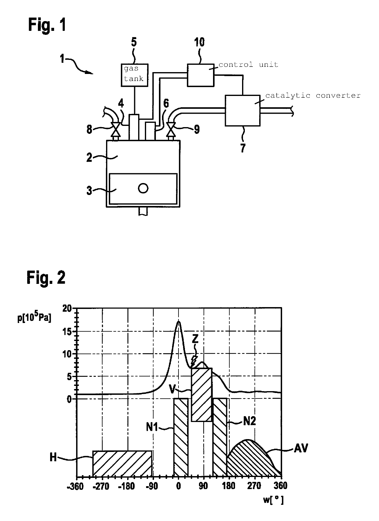
[0016]Below, an example method according to the present invention for the injection of gaseous fuel directly into a combustion chamber 2 of an internal combustion engine 1 in order to heat a catalytic converter 7 is described in detail with reference to FIGS. 1 and 2.

[0017]The heating of catalytic converter 7 is necessary when it has a temperature below a predefined threshold temperature. In comparison with liquid fuels, a required working temperature of the catalytic converter is approximately 100 K higher for gaseous fuels and lies at approximately 420° C.

[0018]As can be gathered from FIG. 1, internal combustion engine 1 includes a piston 3 disposed in combustion chamber 2, an injector 4, and an ignition device 6 such as a spark plug.

[0019]Injector 4 is situated directly on combustion chamber 2 in order to inject gaseous fuel directly into the combustion chamber. Injector 4 is connected to a gas tank 5.

[0020]Catalytic converter 7 is provided in the exhaust tract. In the convention...


PUM


Abstract

A method for injecting gaseous fuel directly into a combustion chamber of an internal combustion engine in order to heat a catalytic converter, the method including: carrying out a main injection of gaseous fuel directly into the combustion chamber; carrying out a first post-injection following the main injection but prior to an ignition, and following the ignition and preferably following the end of combustion in the combustion chamber, carrying out a second post-injection of gaseous fuel into the combustion chamber.

Description

FIELD[0001]The present invention relates to a method for injecting gaseous fuel directly into a combustion chamber of an internal combustion engine in order to heat a downstream catalytic converter; the present invention also relates to a control unit for executing the method.BACKGROUND INFORMATION[0002]In addition to liquid fuels, gaseous fuels are also increasingly used as fuels in internal combustion engines in the more recent past. In comparison with gasoline-operated internal combustion engines, gas-operated internal combustion engines, using natural gas or autogas, for example, are an attractive alternative for realizing savings potentials and reducing a CO2 emission. In addition, potentials with regard to reduced emissions are also obtainable. In an effort to achieve better efficiency, more attempts are also made to realize a direct injection of gas, where the gaseous fuel is injected directly into a combustion chamber of an internal combustion engine. An issue with gaseous f...

Claims


Application Information

Patent Timeline
Patent Type & Authority Patents(United States)
IPC IPC(8): F02D41/40F01N3/20F02D41/02F02D19/06F02D41/38
CPCF02D19/0647F02D41/0255F02D41/405F02D19/0644F01N3/2006Y02T10/36F02D2041/389Y02T10/44Y02T10/30Y02T10/40
Inventor EICHHORN, ALEXANDERLEJSEK, DAVID
Owner ROBERT BOSCH GMBH
Learn More