
Step-bending die device

Active Publication Date: 2019-09-24
FLIGHT CORP
View PDF13 Cites 0 Cited by
  • Summary
  • Abstract
  • Description
  • Claims
  • Application Information

AI Technical Summary

Benefits of technology

The present invention relates to a step-bending process for a workpiece using a die and a punch. The semicircular rotary blades rotate with the bending deformation of the workpiece to make planar contact with the workpiece and prevent edge contact and scratches. The semicircular rotary blades rotate at the same angle during the step bending process, ensuring equal bending of the left and right parts of the workpiece. The adjuster plate regulates the position of the die, and a gap size between vertical lines is obtained to appropriately set the thickness of the step bending portion. The semicircular rotary blades are held tightly in place by tension springs and a tension return spring for accurate contact with the workpiece during processing. The step size can be easily obtained by controlling the stroke amount of the press brake.

Problems solved by technology

However, in the above both prior examples, though a workpiece is put on a die and pressed from above by a punch at step-bending of the workpiece, there has been a problem that product value of the workpiece has been lost because of scratch on the workpiece arisen by that the workpiece is hit on an edge of the die in the process in which the workpiece is deformed plastically by the step-bending die.
Though the constitution that step. sizes can be varied was achieved in JP H0S-317972 A, the inconvenience that the workpiece is scratched during processing remained unresolved.

Method used


Image

  • Step-bending die device
  • Step-bending die device
  • Step-bending die device

Examples


Embodiment Construction

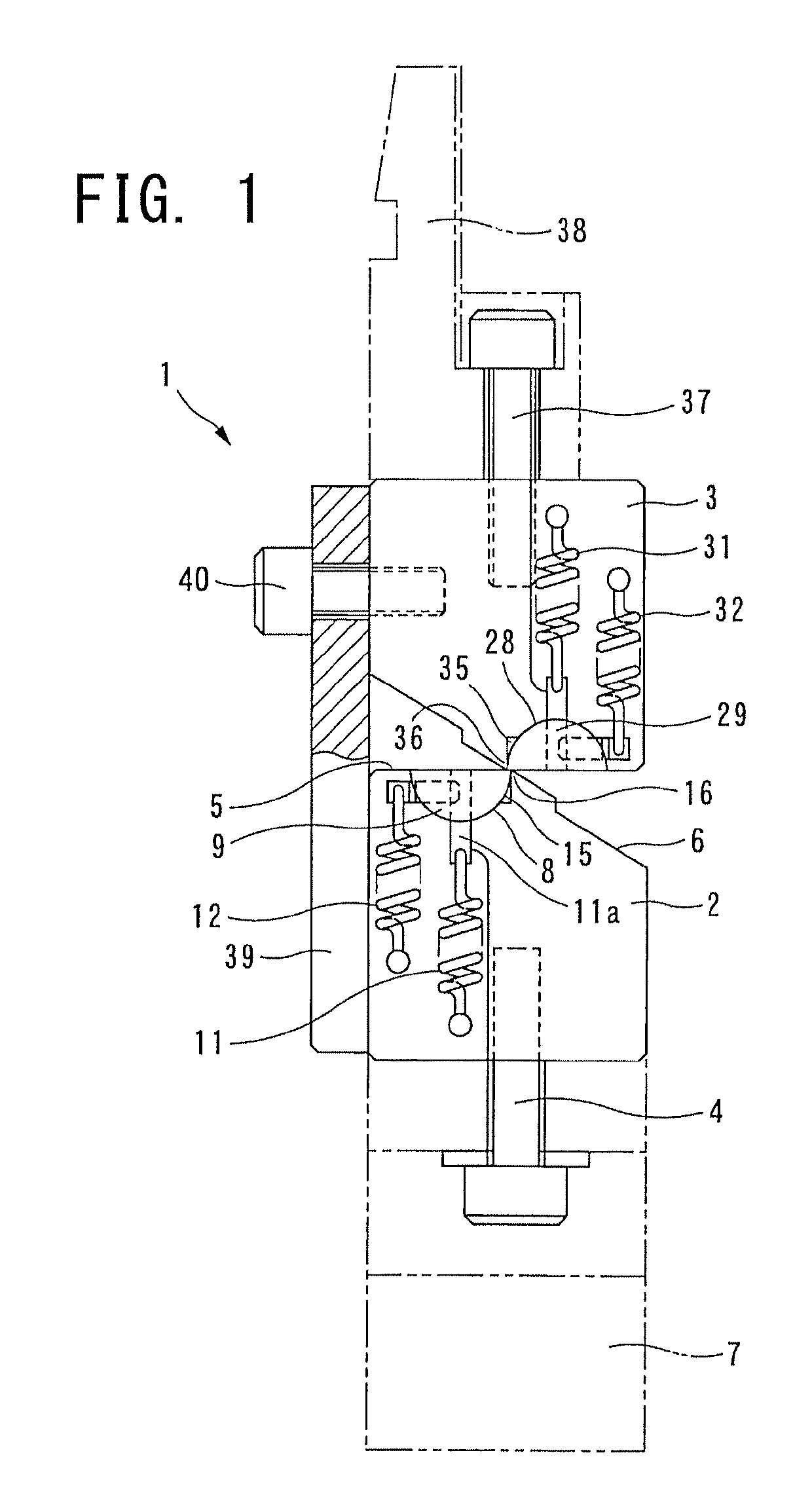
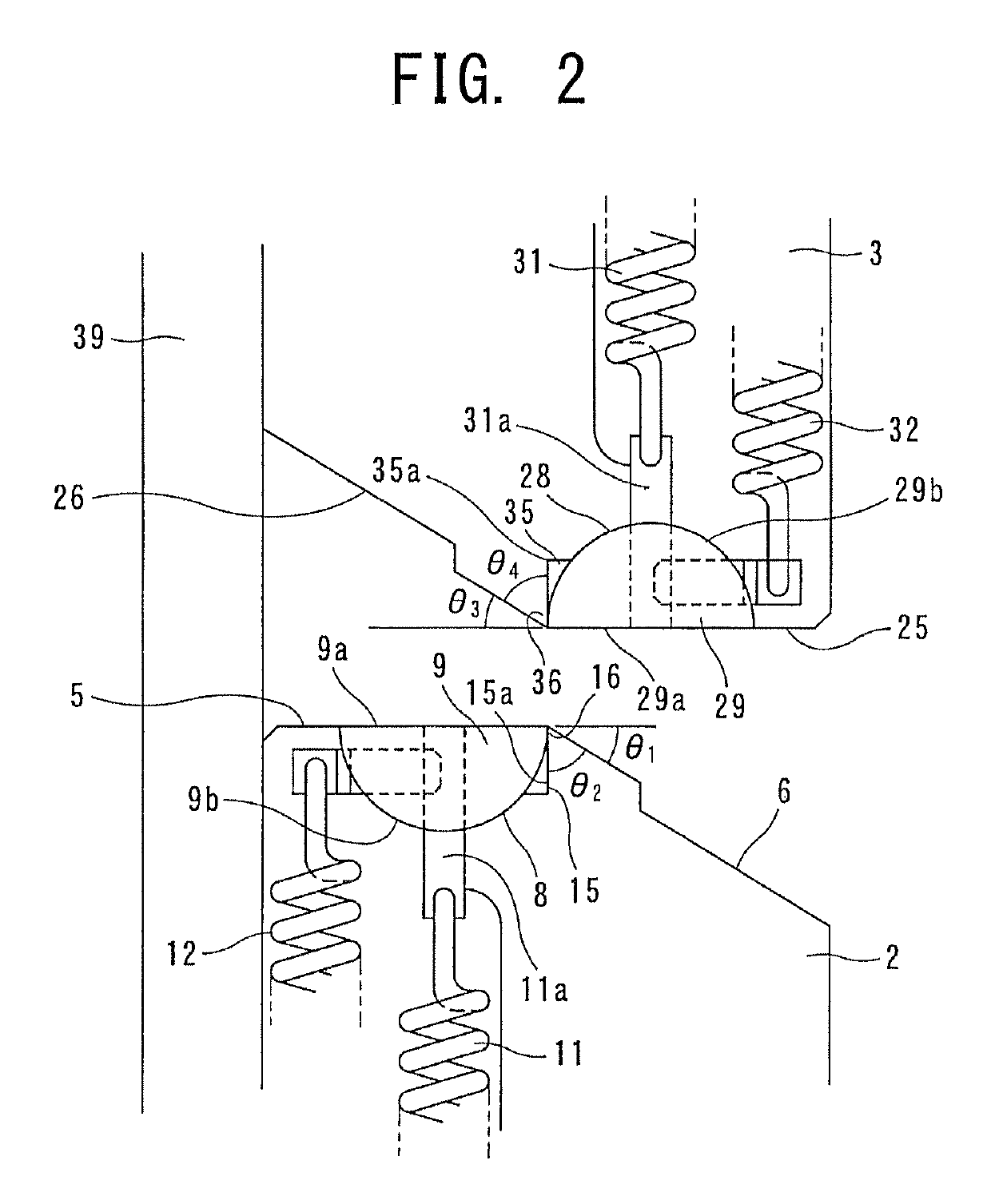
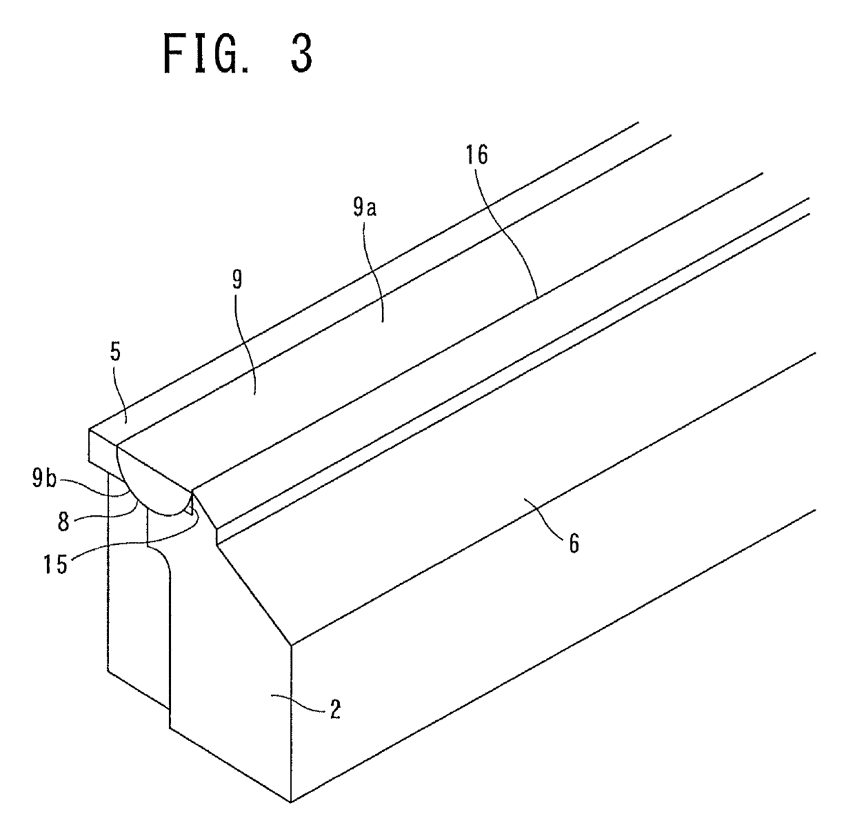
[0027]FIG. 1 to 3 show a step-bending die device according to the present invention, which is attached to a press brake or the like (not shown). This step-bending die device 1 is composed of a die 2 and a punch 3 having a symmetrical structure in the up and down direction. Referring to the die 2 firstly, as shown in FIG. 3, the die 2 has a rectangular parallelepiped shape extending in the lateral direction and has a horizontal surface 5 and an inclined surface 6 on the upper surface thereof, and the horizontal surface and the inclined surface are divided at the center in the short-side direction and extended in the longitudinal direction thereof. This die 2 is fixed to the die base 7 with a fixing bolt 4, but the die 2 can be moved in the horizontal direction (the left and the right direction) when the fixing bolt 4 is loosened.

[0028]A semicircular groove 8 with a semicircular cross section is formed in the longitudinal direction on the horizontal surface 5, and a semicircular rotar...


PUM

PropertyMeasurementUnit
Sizeaaaaaaaaaa
Tensionaaaaaaaaaa

Abstract

In a step-bending die device, the die has a horizontal surface and an inclined surface, forming a semicircular groove with a semicircular cross section along a longitudinal direction on the horizontal surface and installing a semicircular rotary blade rotatably in the semicircular groove. The punch has a horizontal surface and an inclined surface, forming a semicircular groove with a semicircular cross section in a longitudinal direction on the horizontal surface and installing a semicircular rotary blade rotatably in the semicircular groove. Vertical notches at positions changing from the horizontal surfaces to the inclined surfaces are formed in longitudinal directions in the die and the punch so that top portions of the die and the punch are formed. The punch is assembled so that the horizontal surface of the punch faces the inclined surface of the die, and the inclined surface of the punch faces the horizontal surface of the die.

Description

TECHNICAL FIELD[0001]The present invention relates to a step-bending die device used in a step-bending.BACKGROUND OF THE TECHNOLOGY[0002]The shape of the step-bending die is a complicated shape compared with a usual V bending die. The step-bending die is a special die individually designed so as to be adapted to product's shape and thickness. Namely, it was as shown in prior art FIGS. 4 and 5 in Japanese Published Unexamined Patent Application No. H0S-317972 A.[0003]The step-bending die shown in FIG. 4 of the above-mentioned Patent Application is a fixed type for obtained step sizes, and FIG. 5 shows constitution which can vary the step sizes in order to obtain the step size by varying the number of spacers controlling position of an upper block and a lower block.Problem to be Solved by the Invention[0004]However, in the above both prior examples, though a workpiece is put on a die and pressed from above by a punch at step-bending of the workpiece, there has been a problem that prod...

Claims


Application Information

Patent Timeline
IPC IPC(8): B21D5/04B21D5/01
CPCB21D5/01B21D11/18
Inventor MURAI, NOBUTAKAMURAI, SHOICHI
Owner FLIGHT CORP
Learn More