Method for manufacturing laminated core

a manufacturing method and laminate technology, applied in the manufacturing of stator/rotor bodies, electrical apparatus, dynamo-electric machines, etc., can solve the problems of motor performance decline, complicated conveyance, poor workability, etc., to prevent deformation during the conveyance, improve workability, and facilitate handling

Active Publication Date: 2019-09-17
MITSUI HIGH TEC INC
View PDF13 Cites 3 Cited by
  • Summary
  • Abstract
  • Description
  • Claims
  • Application Information

AI Technical Summary

Benefits of technology

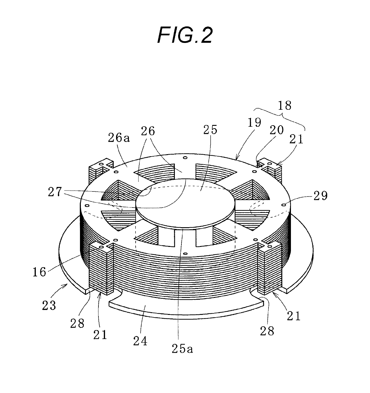
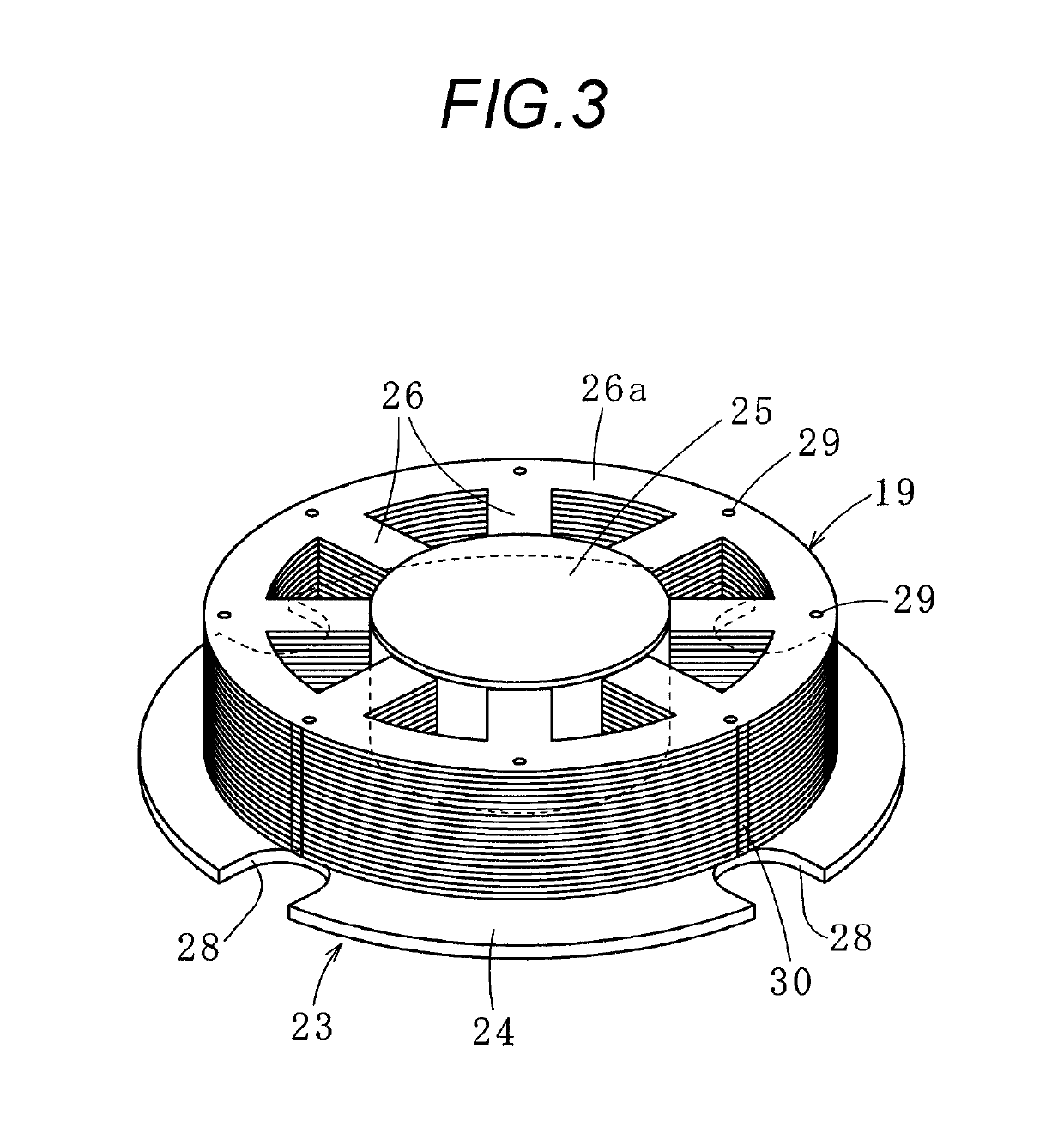
[0017]In the method for manufacturing the laminated iron core according to the present invention, the enlarged iron core pieces including the dummy piece parts are aligned and laminated and the composite laminated iron core is formed and the dummy laminated part is removed and then, the laminated iron core is bonded. As a result, at the time of conveyance, the dummy piece parts can be gripped rather than the iron core pieces, and the iron core pieces can be prevented from being deformed during the conveyance. Also, the enlarged iron core pieces are temporarily bonded by the dummy piece parts and the one composite laminated iron core is formed and thereby, it becomes easy to handle the composite laminated iron core, and workability is also improved. The dummy laminated part is removed and then, the laminated iron core is bonded, with the result that the laminated iron core (body part) is resistant to being influenced by a warp or a strain due to stress caused at the time of bonding the dummy piece parts. Further, before or after the dummy laminated part is removed, the composite laminated iron core or the laminated iron core is placed on the jig and is positioned and the iron core pieces are mutually bonded (for example, the resin bond part is filled with the resin), with the result that accuracy of the completed laminated iron core is increased.
[0018]Here, when the composite laminated iron core with the dummy laminated part attached is placed on the jig, workability of subsequent processing is improved. Also, when the laminated iron core with the dummy laminated part removed is placed on the jig, an influence by caulking is eliminated.

Problems solved by technology

However, the bonding by the caulking has a problem that the iron core pieces conduct in a lamination direction and eddy current loss is caused and motor performance is decreased.
The ejected iron core pieces 80 can be conveyed one by one, but there is a problem that conveyance becomes complicated and trouble with handling in the next step is taken and workability is bad.
Also, when the iron core pieces are conveyed one by one, the iron core piece is directly gripped by conveyance means and the iron core piece with a thin thickness may be deformed, and there is a problem of influencing quality of a product.

Method used


Image

  • Method for manufacturing laminated core
  • Method for manufacturing laminated core
  • Method for manufacturing laminated core

Examples


first embodiment

[0057]Next, the joining piece parts 12 and the joining part 20 for joining the dummy laminated part 21 to the laminated iron core 19 will be described using FIGS. 9(A) to 9(D). In addition, these modified examples can be applied to not only the embodiment described above but also the following embodiments. In the composite laminated iron core 18 used by the method for manufacturing the laminated iron core the joining part 20 has a simple rectangular shape in plan view, but like a first example shown in FIG. 9(A), a narrow part 42 may be formed in a cut position of the joining part 20 (joining piece part 12). Accordingly, the joining part 20 can easily be cut and its cut position is also determined.

[0058]FIG. 9(B) illustrates a shape of the joining part 20 (joining piece part 12) according to a second example. A base of the joining part 20 (accurately, a base of each of the joining piece parts 12) is formed with a thin-walled part 43. This thin-walled part 43 is formed by coining pr...

second embodiment

[0062]FIG. 10 shows a method for manufacturing a laminated iron core according to the present invention. A divided core 46 (one example of the laminated iron core) is formed by removing a dummy laminated part 21 from a unit block iron core 46a. This unit block iron core 46a is formed in a shape in which the composite laminated iron core 18 shown in FIG. 1 is divided in a circumferential direction. This unit block iron core 46a has a divided yoke part 47, a magnetic pole part 48 formed inside the divided yoke part 47, and the dummy laminated part 21 bonded to the outside of the divided yoke part 47 through a joining part 20. A stator laminated iron core used for one motor etc. is formed by annularly arranging a predetermined number of divided cores 46 and forming an annular laminated iron core.

[0063]In the case of positioning this unit block iron core 46a, preferably, a predetermined number of unit block iron cores 46a respectively having the dummy laminated parts 21 are annularly ar...

third embodiment

[0065]Subsequently, a method for manufacturing a laminated iron core according to the present invention will be described with reference to FIGS. 11(A) and 11(B). In this embodiment, plural unit block iron cores 50 are manufactured and the plural unit block iron cores 50 are stacked to form one composite laminated iron core 18. The unit block iron core 50 is formed by laminating unit block iron core pieces 50a, and has a laminated iron core body 51, a unit joining part 52 formed on the periphery of the laminated iron core body 51, and a unit dummy laminated part 53. The manufacturing method of this unit block iron core 50 is similar to that of the composite laminated iron core 18, and it becomes easy to carry the unit block iron core 50 around since the whole thickness of the unit block iron core 50 is thin.

[0066]This unit block iron core 50 has the four unit dummy laminated parts 53 spaced 90 degrees apart. One (hereinafter called 53a) of the unit dummy laminated parts 53 has a sha...


PUM


Abstract

The method includes a step of aligning and laminating enlarged iron core pieces including iron core pieces and dummy piece parts and forming a composite laminated iron core integrally including a dummy laminated part with the dummy piece parts laminated and a laminated iron core, a step of placing and positioning the composite laminated iron core on a jig and removing the dummy laminated part, and a step of mutually bonding the laminated iron core body with the dummy laminated part removed to form the laminated iron core.

Description

[0001]This application is a 371 of PCT / JP2015 / 050330, filing date Jan. 8, 2015.TECHNICAL FIELD[0002]The present invention relates to a method for manufacturing a laminated iron core by removing a dummy laminated part after iron core pieces including dummy piece parts are laminated.BACKGROUND ART[0003]As a method for manufacturing a laminated iron core, for example, a method for laminating iron core pieces with a thickness of 0.3 mm or less and bonding the iron core pieces by caulking etc. is widely implemented. However, the bonding by the caulking has a problem that the iron core pieces conduct in a lamination direction and eddy current loss is caused and motor performance is decreased. Also, in the case of the caulking bonding, the adjacent iron core pieces are pressed in and fitted by the caulking, with the result that shape accuracy is influenced, for example, a warp occurs on a surface of the laminated iron core, or straightness is decreased.[0004]In order to solve the problems ...

Claims


Application Information

Patent Timeline
Patent Type & Authority Patents(United States)
IPC IPC(8): H02K15/02H02K15/03
CPCH02K15/02H02K15/03H02K15/022
Inventor NAGAI, AKIRATEZUKA, SHOGO
Owner MITSUI HIGH TEC INC
Why Eureka
Try Eureka