
Efficient and dependable clock synchronization in hardware

a clock synchronization and clock technology, applied in the field of efficient and reliable clock synchronization in hardware, can solve the problems of affecting the accuracy of the clock, the risk of metastable, and the inability of physical implementations of digital circuits to deterministically avoid, so as to achieve high measurement frequency and time to resolve in memory

Active Publication Date: 2019-09-10
MAX PLANCK GESELLSCHAFT ZUR FOERDERUNG DER WISSENSCHAFTEN EV
View PDF8 Cites 10 Cited by
  • Summary
  • Abstract
  • Description
  • Claims
  • Application Information

AI Technical Summary

Benefits of technology

The invention proposes a new design for a TDC (time-to-digital converter) that is entirely digital, meaning it does not require any analog components. It also requires fewer gates and supports high measurement frequencies compared to traditional delay line TDCs or Nutt interpolators. This design allows for the measurement of time differences between two signals and supports multiple measurements. The TDC output is adaptive, meaning the time taken for the measurement values to resolve in memory can be adjusted without affecting the size or reuse of the TDC for other measurements.

Problems solved by technology

Unfortunately, any way of reading a signal from an unsynchronized clock domain or performing an analog-to-digital conversion incurs the risk of a metastable result; no physical implementation of a digital circuit can deterministically avoid, resolve, or detect metastability (L. R. Marino. General theory of metastable operation.
Accordingly, this approach delays subsequent computations and does not guarantee success.
All known implementations, however, synchronize potentially metastable inputs before computations—a technique that becomes less reliable with increasing operating frequencies, since less time is available for metastability resolution.
Either way, synchronizers do not deterministically guarantee stabilization, and errors are bound to happen eventually when n clocks take n(n−1) samples at, e.g., 1 GHz.

Method used


Image

  • Efficient and dependable clock synchronization in hardware
  • Efficient and dependable clock synchronization in hardware
  • Efficient and dependable clock synchronization in hardware

Examples


Embodiment Construction

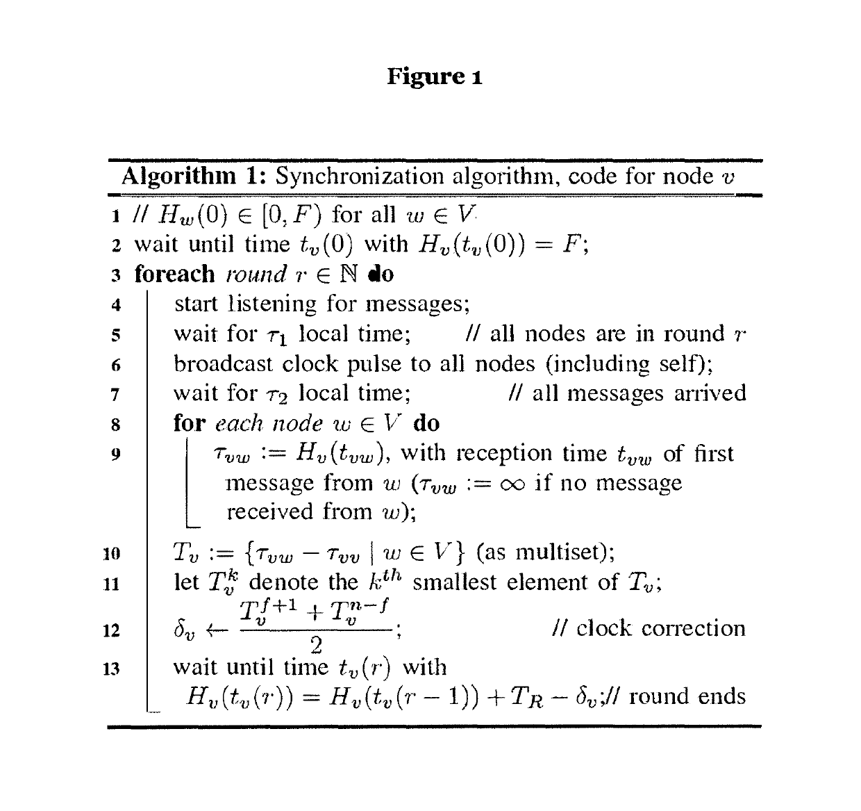
[0040]FIG. 1 shows an algorithm (in pseudocode) for synchronizing clock pulses according to an embodiment of the invention.

[0041]The system in which the algorithm may operate is assumed to consist of a set V of n nodes that are fully connected by (1-bit) broadcast channels. Each node v∈V is a fault-containment region: a single (physical) fault, such as a gate malfunction, does not directly affect correctness of the components outside the fault-containment region that contains the faulty component. Node v comprises a local physical clock Hυ (e.g. a ring oscillator), the circuitry implementing the algorithm's logic for υ, and its outgoing links. This means that communication does not use a shared bus, which would be a single point of failure. Any potential application logic clocked by υ will be part of its fault containment region as well. Thus, any transient or permanent faults of components (in the fault-containment region) of υ affect other nodes only indirectly via communication. ...


PUM


Abstract

The invention comprises a fault-tolerant clock synchronization method with high precision, hardware implementations thereof and the corresponding digital circuits, designed to contain metastability.

Description

RELATED APPLICATIONS[0001]This application is a continuation of International application no. PCT / EP2016 / 002179, filed Dec. 23, 2016, the entire contents of which are hereby fully incorporated herein by reference for all purposes. Application no. PCT / EP2016 / 002179 claims priority from European application no. EP 15 202 534.2, filed Dec. 23, 2015 and U.S. application No. 62 / 272,095, filed Dec. 29, 2015, the entire contents of each of which are hereby fully incorporated herein by reference for all purposes.[0002]The present invention relates to a method for synchronizing a number of clock pulses and metastability-containing circuits used therein.TECHNICAL BACKGROUND AND PRIOR ART[0003]In digital circuits, metastable signals have voltages strictly between logical 0 and logical 1, breaking the abstraction of Boolean logic. Unfortunately, any way of reading a signal from an unsynchronized clock domain or performing an analog-to-digital conversion incurs the risk of a metastable result; n...

Claims


Application Information

Patent Timeline
Patent Type & Authority Patents(United States)
IPC IPC(8): H03L7/099G04F10/00
CPCG04F10/005H03L7/0995
Inventor LENZEN, CHRISTOPHFÜGGER, MATTHIASKINALI, ATTILAFRIEDRICHS, STEPHANMEDINA, MOTI
Owner MAX PLANCK GESELLSCHAFT ZUR FOERDERUNG DER WISSENSCHAFTEN EV
Learn More