Voltage sensor

a voltage sensor and voltage technology, applied in the field of voltage sensors, can solve problems such as complicated assembly, and achieve the effect of improving the accuracy of voltage measurement and measuring accuracy

Active Publication Date: 2019-09-03
YAZAKI CORP +1
View PDF11 Cites 0 Cited by
  • Summary
  • Abstract
  • Description
  • Claims
  • Application Information

AI Technical Summary

Benefits of technology

[0011]According to the voltage sensor (1) of the present invention, because the fixed electrodes are provided against the circular or roughly circular oscillator, and at positions different from the fixed electrodes, the drive electrodes to which AC drive voltages are applied are included, the circular or roughly circular oscillator oscillates to be crushed or pushed out by the drive electrodes, and the amplitude can be lowered as compared to the equally-advancing oscillator. Thus, because the influence of gas damping can be reduced, and the oscillator works stably, a noise is controlled and the signal Q factor (optical measurement) at the time of the resonance and the signal change (electrical measurement) can be raised. Because the parts such as the Pockels element, the quarter wave plate, the polarizer, the analyzer and the like are not necessary, and the alignment of the optical axis is not necessary either, the increase of the part number and complicatedness of the assembling can be prevented. Therefore, while the increase of the part number and the complicatedness of the assembling are prevented, the signal Q factor obtained by the optical measurement and the signal change obtained by the electrical measurement are raised and the voltage measurement precision can be improved.
[0013]According to this voltage sensor (2), because the support member is connected to at least one of the four knobs where the oscillating amplitude is minimized among the oscillator, an energy loss of the oscillation can be lower than a case of connecting to other points.
[0015]According to this voltage sensor, because the fixed electrodes are formed with the comb-like grooves along the oscillation direction of the oscillator, gas escapes in parallel with the vibration, and the influence of gas damping can be controlled further.
[0017]According to this voltage sensor (4), because the substrate is provided with the opening in a top view in the area where the oscillator, the fixed electrodes and the drive electrodes are formed, gas may escape at the time of oscillation from the opening of the substrate, and the influence of gas damping can be controlled further.
[0019]According to this voltage sensor, because the two drive electrodes are placed at the positions opposite to each other relative to the center of the oscillator, and AC voltages of the same phase are applied, the circular or roughly circular oscillator can oscillate efficiently to be crushed or pushed out. Furthermore, because the two fixed electrodes are placed at the positions perpendicular to the direction linking the two drive electrodes, by placing the two fixed electrodes to face parts of the oscillator where oscillation amount is the biggest, when the voltage to be measured is applied to the two fixed electrodes, the change of the resonance frequency of the oscillator can be more remarkable, and the measurement accuracy can be proved.
[0020]According to the present invention, a voltage sensor can be provided so that improvement of the voltage measurement precision becomes possible since the Q factor (quality factor) obtained by the optical measurement and the signal change obtained by the electrical measurement are raised.

Problems solved by technology

As a result, assembling is complicated.

Method used


Image

  • Voltage sensor
  • Voltage sensor
  • Voltage sensor

Examples


Embodiment Construction

[0033]A preferred embodiment of the present invention is described based on the figures as follows, but the present invention is not limited to the following embodiment.

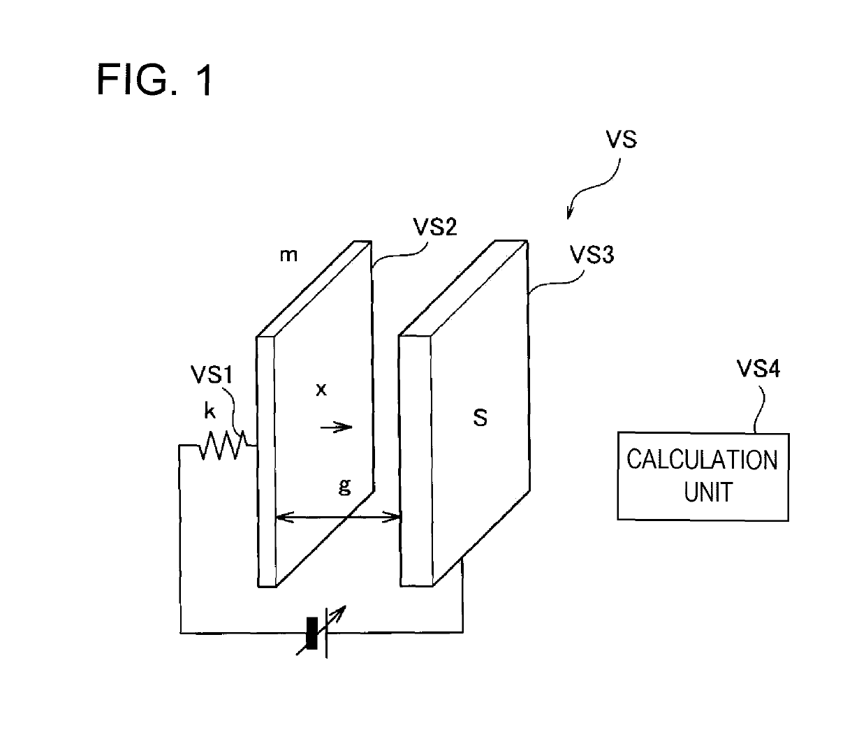
[0034]FIG. 1 is a basic configuration diagram indicating the principle of a voltage sensor according to an embodiment of the present invention. As shown in FIG. 1, a voltage sensor VS according to the basic principle includes a mechanical suspension VS1, an oscillator VS2, a fixed electrode VS3, and a calculation unit VS4.

[0035]The suspension VS1 supports the oscillator VS2. A spring constant of this suspension VS1 is assumed as k. The oscillator VS2 is a plate electrode supported by the suspension VS1, and the oscillator VS2 is oscillateable due to elasticity of the suspension VS1. The mass of this oscillator VS2 is assumed as m.

[0036]The fixed electrode VS3 is a plate electrode which is placed to be opposed to the oscillator VS2 with a gap, and has the relation of parallel plate electrodes with the oscillator VS2. ...


PUM


Abstract

A voltage sensor includes an oscillator that has a circular or roughly circular shape and is supported by a mechanical support member, a fixed electrode that has a predetermined gap between the oscillator and the fixed electrode, and a drive electrode that is placed at a position different from the fixed electrode across the oscillator, and to which an AC drive voltage is applied to make the oscillator oscillate. In the voltage sensor, an electrostatic attractive force acts on the oscillator by applying a voltage to the fixed electrode, and a resonance frequency of the oscillator changes.

Description

CROSS REFERENCE TO RELATED APPLICATION[0001]This application is based on Japanese Patent Application No. 2016-093214 filed on May 6, 2016, the contents of which are incorporated herein by reference.BACKGROUND1. Technical Field[0002]The present invention relates to a voltage sensor.2. Background Art[0003]Traditionally, a voltage sensor that includes a Pockels element, a quarter wave plate, a polarizer, an analyzer and the like is proposed. With this voltage sensor, an optical signal output from a source of light is polarized by the polarizer, and incident on the Pockels element, and an optical modulation that responds to the size of a voltage is received with the Pockels element. The optical signal that receives optical modulation is transmitted to the analyzer through the quarter wave plate. The optical signal output by the analyzer is received and detected by a predetermined optical receiver, and the voltage applied to the Pockels element can be measured (for example, refer to JP-A...

Claims


Application Information

Patent Timeline
Patent Type & Authority Patents(United States)
IPC IPC(8): G01R31/00G01R15/24
CPCG01R15/242
Inventor ISHIHARA, HIROKIISHII, MAKOTOSASAKI, MINORU
Owner YAZAKI CORP
Why Eureka
Try Eureka