
Control circuit for suppressing electromagnetic interference signals

a control circuit and signal technology, applied in the field of electromagnetic interference signal suppression, can solve the problems of undesirable performance variation during production, difficult to achieve substantial or complete cancellation, and introduce undesirable side effects, and achieve the effect of easy integration into the integrated circui

Active Publication Date: 2019-08-27
ANAPP TECH LTD
View PDF2 Cites 4 Cited by
  • Summary
  • Abstract
  • Description
  • Claims
  • Application Information

AI Technical Summary

Benefits of technology

The invention provides an improved control circuit for suppressing electromagnetic interference (noise) signals. The circuit includes a variable gain filter with a variable gain factor that reduces the electromagnetic interference signal. The circuit is controlled by a controller that receives a signal indicative of the output signal and adjusts the gain factor to minimize the electromagnetic interference. The circuit can be easily integrated into an integrated circuit.

Problems solved by technology

In practice, however, a substantial or complete cancellation can be difficult to achieve.
These factors cause undesirable performance variation during production as well as throughout the operating life of the circuit.
Another difficulty with the implementation of electromagnetic interference suppression circuits relates to feedback control.
In particular, the use of amplifiers or like circuit components with high gain and good phase characteristic would easily introduce undesirable side effects such as instability and oscillation to the circuit.

Method used


Image

  • Control circuit for suppressing electromagnetic interference signals
  • Control circuit for suppressing electromagnetic interference signals
  • Control circuit for suppressing electromagnetic interference signals

Examples


Embodiment Construction

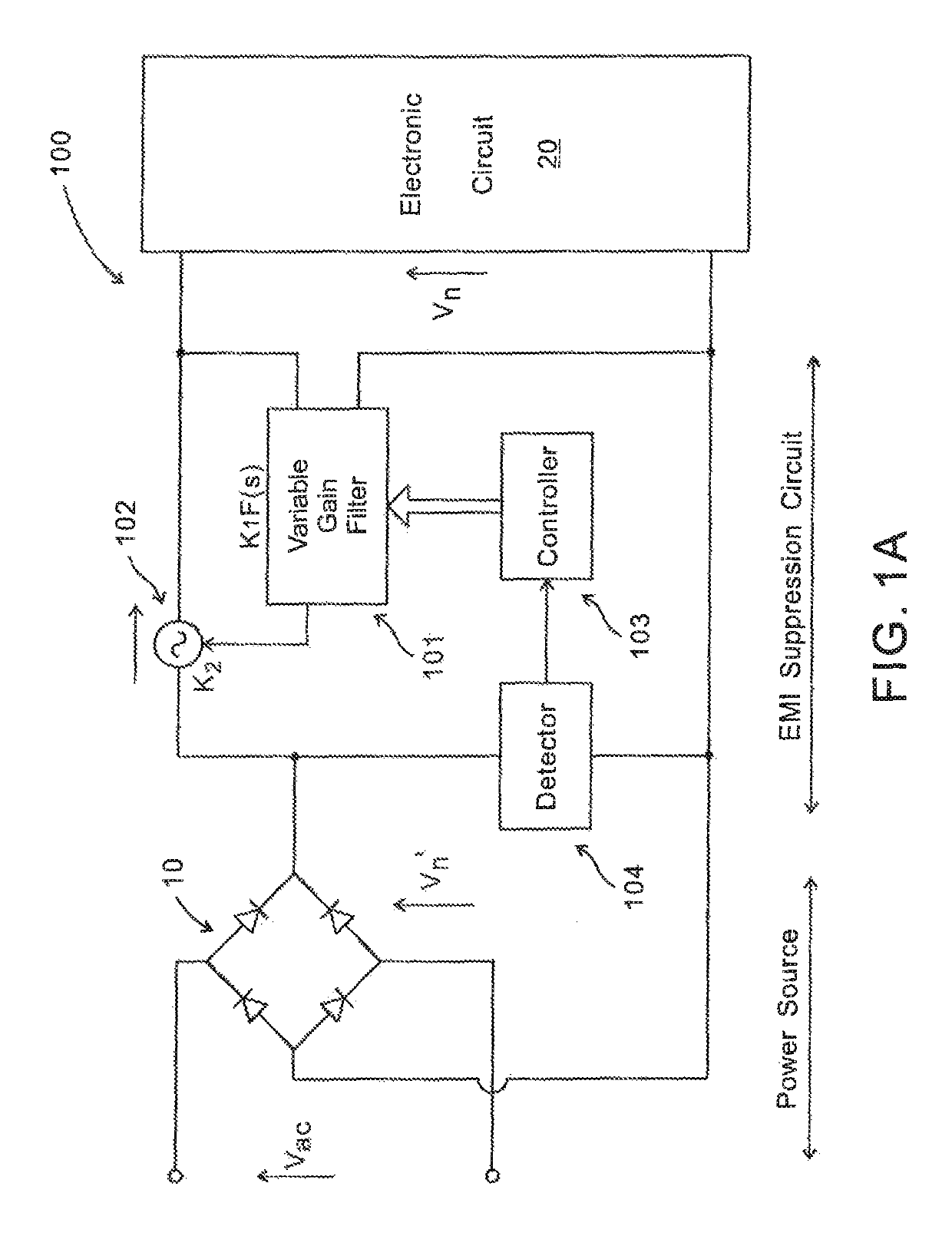
[0031]FIG. 1A shows a control circuit 100 arranged between a power supply line and a power return line for suppressing differential mode electromagnetic interference signals in one embodiment of the invention. In FIG. 1A, the control circuit 100 is arranged between a power supply circuit 10 (labeled as “Power Source”) and a load circuit 20 (labeled as “Electronic circuit”). The control circuit 100 has an input connected with the load circuit 20 and an output connected with the power supply circuit 10. In this embodiment, the power supply circuit 10 includes a diode rectifier bridge, operably connected with an AC power source (not shown).

[0032]The control circuit 100 includes a variable gain filter circuit 101 arranged to receive, at an input of the control circuit 100, an electromagnetic interference signal in the form of an electromagnetic interference signal voltage vn and to provide a signal to a controlled voltage source 102. The variable gain filter circuit 101 is preferably a ...


PUM


Abstract

A control circuit for suppressing electromagnetic interference signal has an input and an output and a variable gain filter circuit with a first gain factor that is variable. The variable gain filter circuit receives a signal indicative of an electromagnetic interference signal and outputs a signal to a controlled signal source, which a second gain factor. The control circuit also has a controller operably connected to the variable gain filter circuit. The controller receives a signal indicative of an output signal at the output of the control circuit and outputs a control signal to the variable gain filter circuit. The control signal is based on the signal indicative of the output signal at the output of the control circuit, and the control signal controls the first gain factor and reduces the electromagnetic interference signal.

Description

TECHNICAL FIELD[0001]The invention relates to suppression of electromagnetic interference signals conducted in signal or power lines in electric circuits.BACKGROUND[0002]Electromagnetic interference suppression circuits are known and are commonly used for suppressing conducted electromagnetic interference signals present on a signal or power line. These conducted electromagnetic interference signals can be classified into differential mode electromagnetic interference signals, which are conducted on the power supply line and the power return line in opposite directions, and common mode electromagnetic interference signals, which are conducted on the power supply line and the power return line in the same direction.[0003]In theory, an electromagnetic interference suppression circuit is able to generate a suppression signal that can reduce or even eliminate the unwanted electromagnetic interference signal. For the best suppression performance, the generated suppression signal should b...

Claims


Application Information

Patent Timeline
Patent Type & Authority Patents(United States)
IPC IPC(8): H02M1/44H03H11/12
CPCH02M1/44H03H11/126H03H2210/025H03H2210/028H04B15/00H03H11/1291
Inventor POON, FRANKI NGAI KITCHAN, PETER ON BON
Owner ANAPP TECH LTD
Learn More