Catheter

a catheter and catheter technology, applied in the field of catheters, can solve the problems of high rigidity in the region, marker is provided than the rigidity of other regions, and at the border area, etc., to prevent/reduce the breaking of the catheter, prevent excessive concentration of stress, and be flexible enough

Active Publication Date: 2019-08-27
ASAHI INTECC CO LTD
View PDF20 Cites 0 Cited by
  • Summary
  • Abstract
  • Description
  • Claims
  • Application Information

AI Technical Summary

Benefits of technology

[0012]In the disclosed embodiments, even when the catheter is inserted and curved in a patient's blood vessel, it is possible to prevent excessive concentration o

Problems solved by technology

However, the above-described conventional catheters, including the catheters of Patent Literature 1 and Patent Literature 2, have a problem in that the rigidity is much higher in the region where the radiopaque marker is provided than the rigidity of other regions.
This causes a break in rigidity at a border area between the portion where the radiopaque marker is provided and a portion where the radiopaque marke

Method used


Image

  • Catheter
  • Catheter
  • Catheter

Examples


Embodiment Construction

[0022]The catheter according to the disclosed embodiments will be described with reference to the enclosed drawings. The present disclosure shall not be limited, to the embodiments provided below, and modifications in design can appropriately be made.

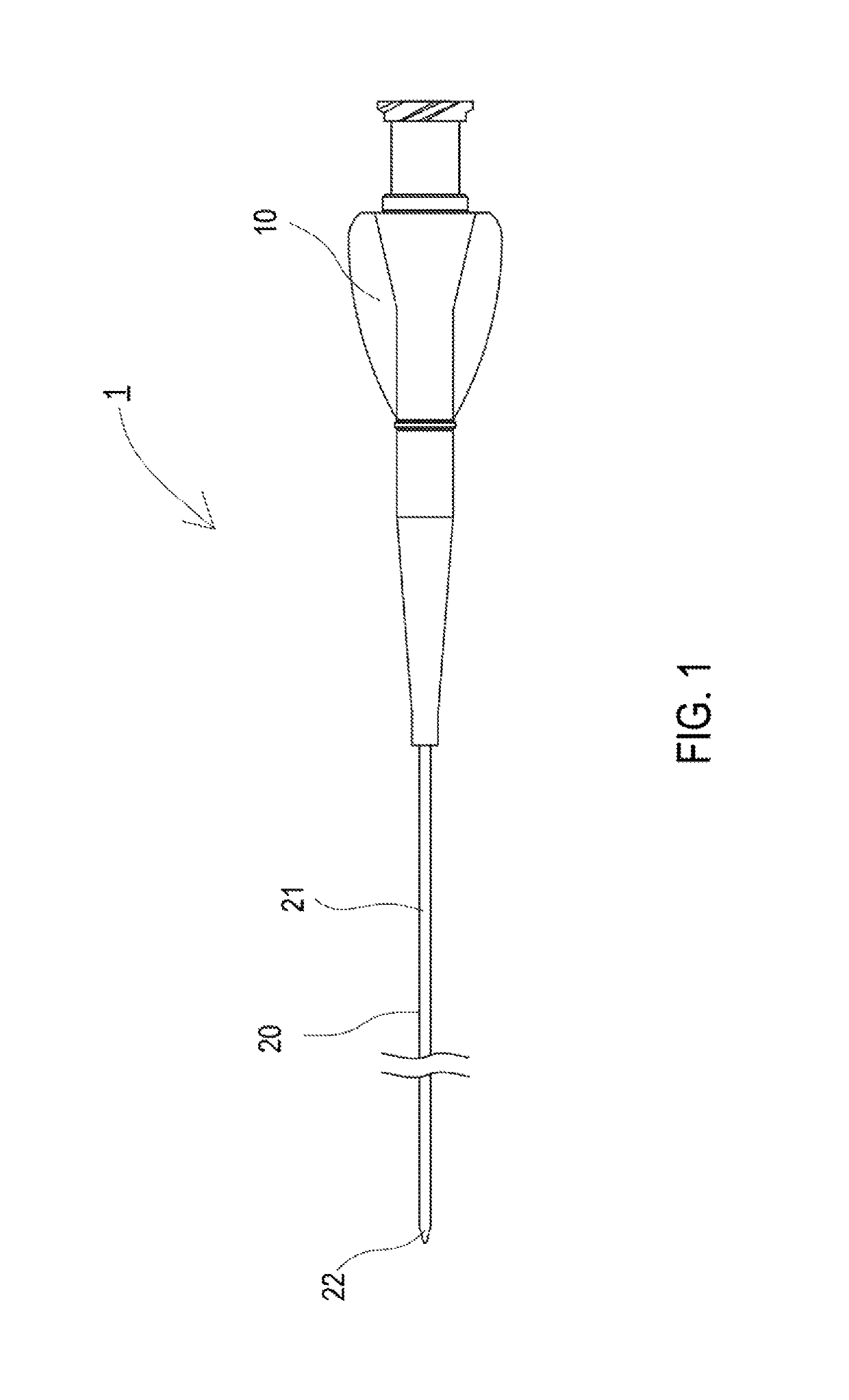
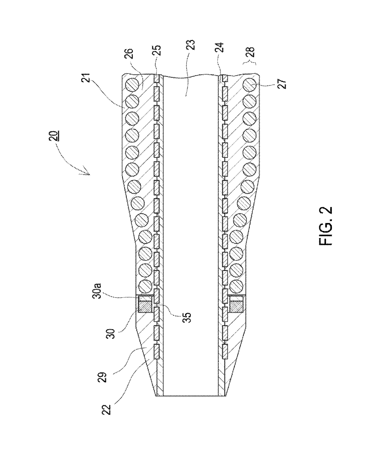
[0023]FIG. 1 is a plan view of a catheter according to embodiments of the present disclosure, and FIG. 2 is a partial enlarged section of the catheter of FIG. 1.

[0024]As illustrated in FIG. 1, catheter 1 includes an operation part 10, which is operated by a technician, and a catheter tube 20 (corresponding to a “tubular body”), which is connected to a distal end of the operation part 10. Moreover, the catheter tube 20 includes a catheter main body part 21, extending from the operation part 10, and a distal end tip 22, positioned on the distal end side of the catheter main body part 21. Each of the vicinity of the distal end of the catheter main body part 21 and the vicinity of the distal end of the distal end tip 22 has a tapered form i...


PUM

PropertyMeasurementUnit
Radiopacityaaaaaaaaaa

Abstract

A catheter that prevents excessive concentration of stress while providing sufficient flexibility to a distal end portion of the catheter, even when the catheter is inserted and curved in patient's a blood vessel. Thus, breakage of the catheter at a radiopaque marker is prevented/reduced. The catheter includes a catheter tube and the radiopaque marker, which is disposed in the catheter tube. The radiopaque marker is fixed in the catheter so that a gap is provided between the radiopaque marker and the catheter tube in a radial direction of the catheter tube.

Description

CROSS REFERENCE TO RELATED APPLICATION[0001]This application is a Continuation of U.S. patent application Ser. No. 15 / 042,303 application, filed Feb. 12, 2016, which claims priority to Japanese Patent Application No. 2015-242283, filed in the Japan Patent Office on Dec. 11, 2015, and Japanese Patent Application No. 2015-026948, filed in the Japan Patent Office on Feb. 13, 2015, the entire contents of which are incorporated by reference.BACKGROUND[0002]The disclosed embodiments relate to a catheter for medical use.[0003]Conventional balloon catheters include a radiopaque marker at a distal end of the catheter so that a distal end position of the catheter can be visually observed during procedures.[0004]For example, Patent Literature 1 (identified below) discloses a catheter including an elongate main tubular body 10 with a polytetrafluoroethylene core 16 and a polyurethane outer jacket 18, which covers the polytetrafluoroethylene core 16. Additionally, the catheter includes a soft po...

Claims


Application Information

Patent Timeline
IPC IPC(8): A61M25/00A61M25/01
CPCA61M25/0012A61M25/005A61M25/0108A61M2025/0059A61M25/0026A61M25/0045A61M2025/0039
Inventor MATSUMOTO, SATORUHORI, TAKAYUKI
Owner ASAHI INTECC CO LTD
Why Eureka
Try Eureka