
System for maintaining reversible dynamic range control information associated with parametric audio coders

a parametric audio coder and dynamic range control technology, applied in the field of audiovisual media distribution, can solve problems such as the limitation of such potential improvements

Active Publication Date: 2019-08-20
DOLBY LAB LICENSING CORP +1
View PDF79 Cites 0 Cited by
  • Summary
  • Abstract
  • Description
  • Claims
  • Application Information

AI Technical Summary

Benefits of technology

The invention is about an adaptive distribution format for audiovisual media distribution that allows for both a higher-bitrate and a lower-bitrate mode as well as seamless mode transitions during decoding. The invention also addresses the issue of dynamic range control in relation to adaptive bitrate coding methods. The invention provides a solution for improving the efficiency and compatibility of existing adaptive distribution formats with legacy decoders. The technical effects of the invention include improved bandwidth efficiency, computational efficiency, error resilience, algorithmic delay, and further, in audiovisual media distribution, as to how noticeable a bitrate switching event is to a person enjoying the decoded media.

Problems solved by technology

The fact that legacy decoders can be expected to remain in use parallel to newer, dedicated equipment poses a limitation on such potential improvements insofar as backward compatibility must be maintained.

Method used


Image

  • System for maintaining reversible dynamic range control information associated with parametric audio coders
  • System for maintaining reversible dynamic range control information associated with parametric audio coders
  • System for maintaining reversible dynamic range control information associated with parametric audio coders

Examples


Embodiment Construction

I. Overview

[0015]As used herein, an “audio signal” may be a pure audio signal or an audio part of an audiovisual signal or multimedia signal.

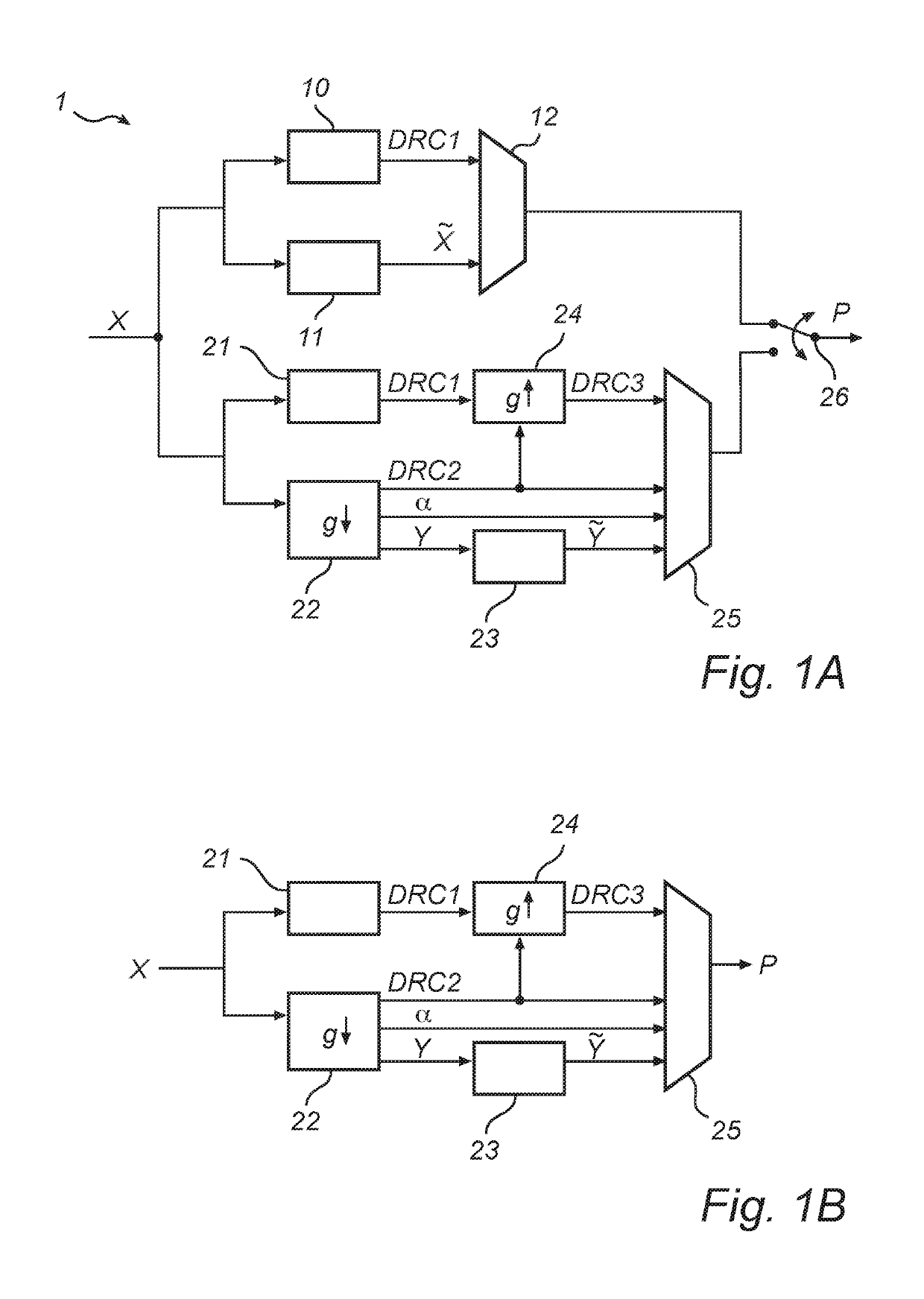
[0016]An example embodiment of the present invention proposes methods and devices enabling distribution of audiovisual media in a bandwidth-economical manner. In particular, an example embodiment proposes a coding format for audiovisual media distribution that allows both legacy receivers and more recent equipment to output an audio portion having a consistent dialogue level. In particular, an example embodiment proposes a coding format with adaptive bitrate, wherein a switching between two bitrate values need not be accompanied by a sharp dialogue level change, which may otherwise be a perceptible artefact in the audio signal or the audio portion of the signal during playback.

[0017]An example embodiment of the invention provides an encoding method, encoder, decoding method, decoder, computer-program product and a media coding format with the f...


PUM


Abstract

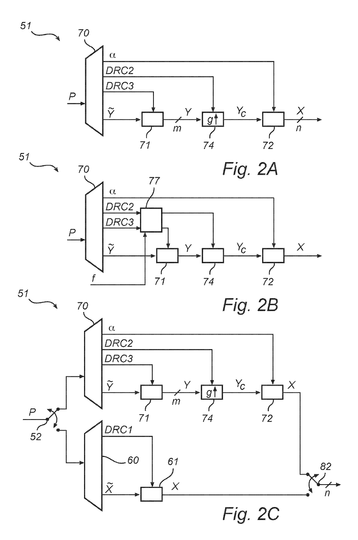
On the basis of a bitstream (P), an n-channel audio signal (X) is reconstructed by deriving an m-channel core signal (Y) and multichannel coding parameters (α) from the bitstream, where 1≤m<n. Also derived from the bitstream are pre-processing dynamic range control, DRC, parameters (DRC2) quantifying an encoder-side dynamic range limiting of the core signal. The n-channel audio signal is obtained by parametric synthesis in accordance with the multichannel coding parameters and while cancelling any encoder-side dynamic range limiting based on the pre-processing DRC parameters.In particular embodiments, the reconstruction further includes use of compensated post-processing DRC parameters quantifying a potential decoder-side dynamic range compression. Cancellation of an encoder-side range limitation and range compression are preferably performed by different decoder-side components. Cancellation and compression may be coordinated by a DRC pre-processor.

Description

CROSS-REFERENCE TO RELATED APPLICATIONS[0001]This application is a divisional of U.S. patent application Ser. No. 16 / 039,608, filed Jul. 19, 2018, which is a continuation of U.S. patent application Ser. No. 15 / 881,393 (now U.S. Pat. No. 10,074,379), filed Jan. 26, 2018, which is a divisional of U.S. patent application Ser. No. 15 / 648,733 (now U.S. Pat. No. 9,881,629), filed Jul. 13, 2017, which is a divisional of U.S. patent application Ser. No. 15 / 178,102 (now U.S. Pat. No. 9,721,578), filed Jun. 9, 2016, which is a continuation of U.S. patent application Ser. No. 14 / 399,861 (now U.S. Pat. No. 9,401,152), filed Nov. 7, 2014 which in turn is the 371 national stage of PCT Application No. PCT / US2013 / 039344, filed May 2, 2013. PCT Application No. PCT / US2013 / 039344 claims priority to U.S. Provisional Patent Application No. 61 / 649,036 filed May 18, 2012, U.S. Provisional Patent Application No. 61 / 664,507, filed Jul. 25, 2012 and U.S. Provisional Patent Application No. 61 / 713,005, filed O...

Claims


Application Information

Patent Timeline
IPC IPC(8): G10L19/24G10L19/16G10L19/18G10L19/008
CPCG10L19/24G10L19/18G10L19/167G10L19/008E21B21/003E21B33/138E21B41/00
Inventor RIEDMILLER, JEFFREYROEDEN, KARL J.KJOERLING, KRISTOFERPURNHAGEN, HEIKOMELKOTE, VINAYSEHLSTROM, LEIF
Owner DOLBY LAB LICENSING CORP
Learn More