
Optical member and backlight unit including same

a backlight unit and optical member technology, applied in the field of optical members, can solve problems such as generating mura, and achieve the effect of increasing the size of the optical member

Active Publication Date: 2019-08-13
SUZHOU LEKIN SEMICON CO LTD
View PDF20 Cites 0 Cited by
  • Summary
  • Abstract
  • Description
  • Claims
  • Application Information

AI Technical Summary

Benefits of technology

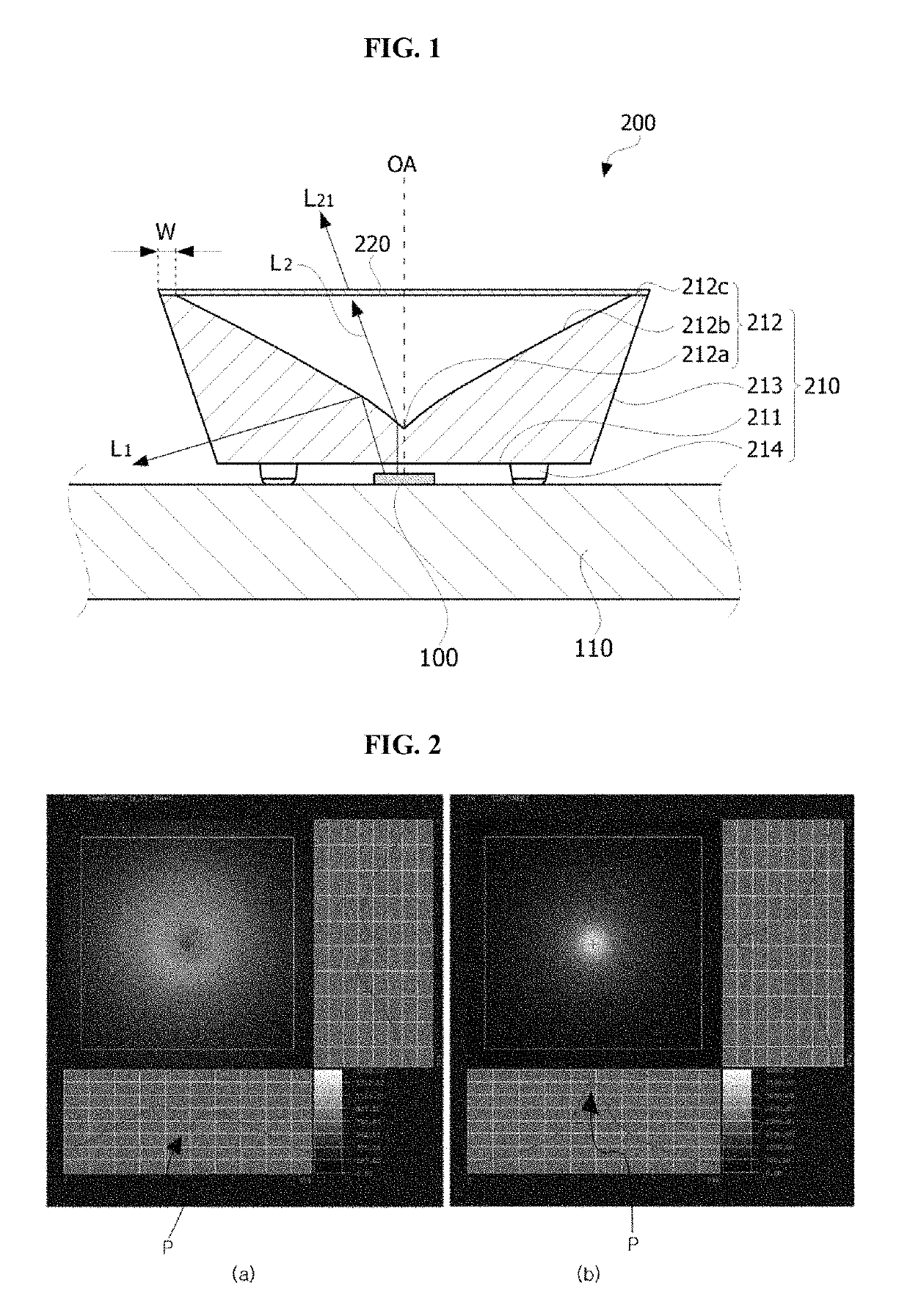
The invention aims to reduce the concentration of light on the center of a lens by adding a cover to the lens, which results in better illumination uniformity. This allows for increased coverage of an area with a single light emitting device and optical member.

Problems solved by technology

However, when a thickness of a BLU is 10 mm or less, the center of a lens becomes bright, resulting in a problem of generating Mura.

Method used


Image

  • Optical member and backlight unit including same
  • Optical member and backlight unit including same
  • Optical member and backlight unit including same

Examples


Embodiment Construction

[0025]As the present invention is amenable to various modifications and alternative forms of embodiments, certain particular embodiments will be described in connection with drawings. However, it should be understood that the intention is not to limit the invention to the particular embodiments described but is to cover all modifications, equivalents, and alternatives falling within the technical spirit and scope of the invention.

[0026]Although the terms first, second, etc. may be used to describe various elements, these elements are not limited by these terms. These terms are only used to distinguish one element from another. For example, a first element could be termed a second element, and, similarly, a second element could be termed a first element, without departing from the scope of exemplary embodiments. The term “and / or” includes any and all combinations of one or more of the associated listed items.

[0027]In addition, suffix terms including “module” and “unit” added to eleme...


PUM

PropertyMeasurementUnit
light transmittanceaaaaaaaaaa
widthaaaaaaaaaa

Abstract

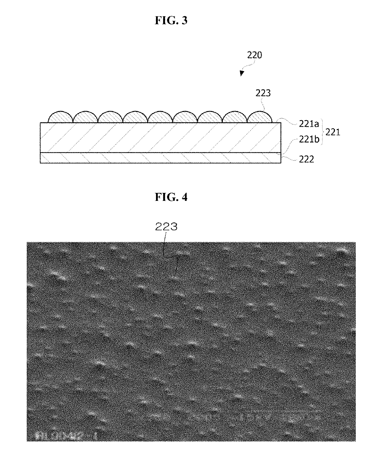
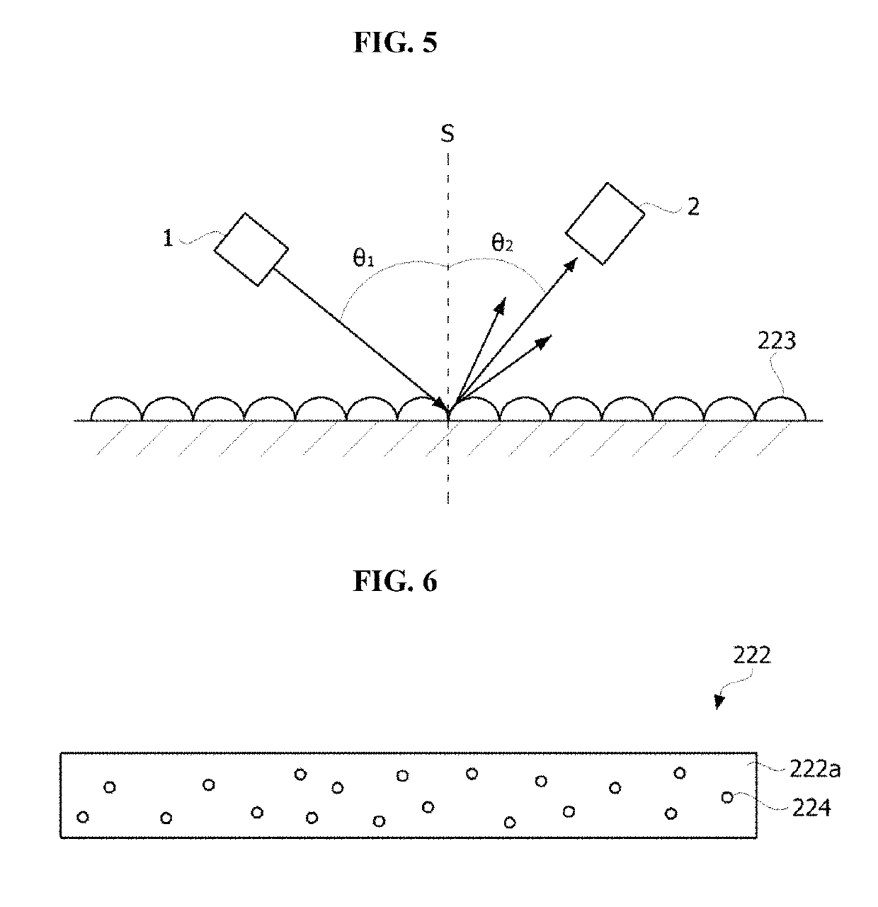
Disclosed are an optical member and a backlight unit including the same, the optical member comprising: a lens including a first optical surface, a second optical surface facing the first optical surface, and a third optical surface interconnecting the first optical surface and second optical surface; and a cover which is disposed on the second optical surface and has a light transmittance of 5 to 30%.

Description

CROSS-REFERENCE TO RELATED PATENT APPLICATIONS[0001]This application is a U.S. National Stage Application under 35 U.S.C. § 371 of PCT Application No. PCT / KR2015 / 003605, filed Apr. 10, 2015, which claims priority to Korean Patent Application No. 10-2014-0043067, filed Apr. 10, 2014, whose entire disclosures are hereby incorporated by reference.TECHNICAL FIELD[0002]The present invention relates to an optical member which controls light emitted from a light emitting device.BACKGROUND ART[0003]A liquid crystal display (LCD) is a device which converts various types of electrical information generated from various types of devices into visual information and displays the visual information, using changes in liquid crystal transmittance according to applied voltages.[0004]Because the LCD is not self-emissive, the LCD is provided with a backlight unit (BLU) serving as a light emitting device which provides light to rear of a liquid crystal panel that displays images.[0005]The BLU may be cl...

Claims


Application Information

Patent Timeline
Patent Type & Authority Patents(United States)
IPC IPC(8): F21V5/04G02B19/00G02F1/1335F21Y105/10F21Y115/10
CPCG02F1/133606F21V5/04G02B19/0028G02B19/0061G02F1/133603G02B19/0071G02F2202/28F21Y2105/10F21Y2115/10G02F2001/133607G02F1/133607
Inventor KIM, KYUNG JIN
Owner SUZHOU LEKIN SEMICON CO LTD
Learn More