Turbine ring assembly with support when cold and when hot

a technology of ring assembly and support, which is applied in the direction of mechanical equipment, leakage prevention, machines/engines, etc., can solve the problem that the retention of ring segments by this co-operation between portions in relief cannot be guaranteed, and achieve the effect of reducing mechanical stresses

Active Publication Date: 2019-08-13
SN DETUDE & DE CONSTR DE MOTEURS DAVIATION S N E C M A
View PDF6 Cites 26 Cited by
  • Summary
  • Abstract
  • Description
  • Claims
  • Application Information

AI Technical Summary

Benefits of technology

[0016]The use of such sloping portions in the annular flanges of the ring support structure contributes to compensating for differences in expansion between the annular flanges and the ring sector tabs, thereby reducing mechanical stresses to which the ring sectors are subjected in operation.

Problems solved by technology

The retention of the ring sectors by this co-operation between portions in relief can no longer be ensured when hot because of the expansion of the annular flanges.

Method used


Image

  • Turbine ring assembly with support when cold and when hot
  • Turbine ring assembly with support when cold and when hot
  • Turbine ring assembly with support when cold and when hot

Examples


Embodiment Construction

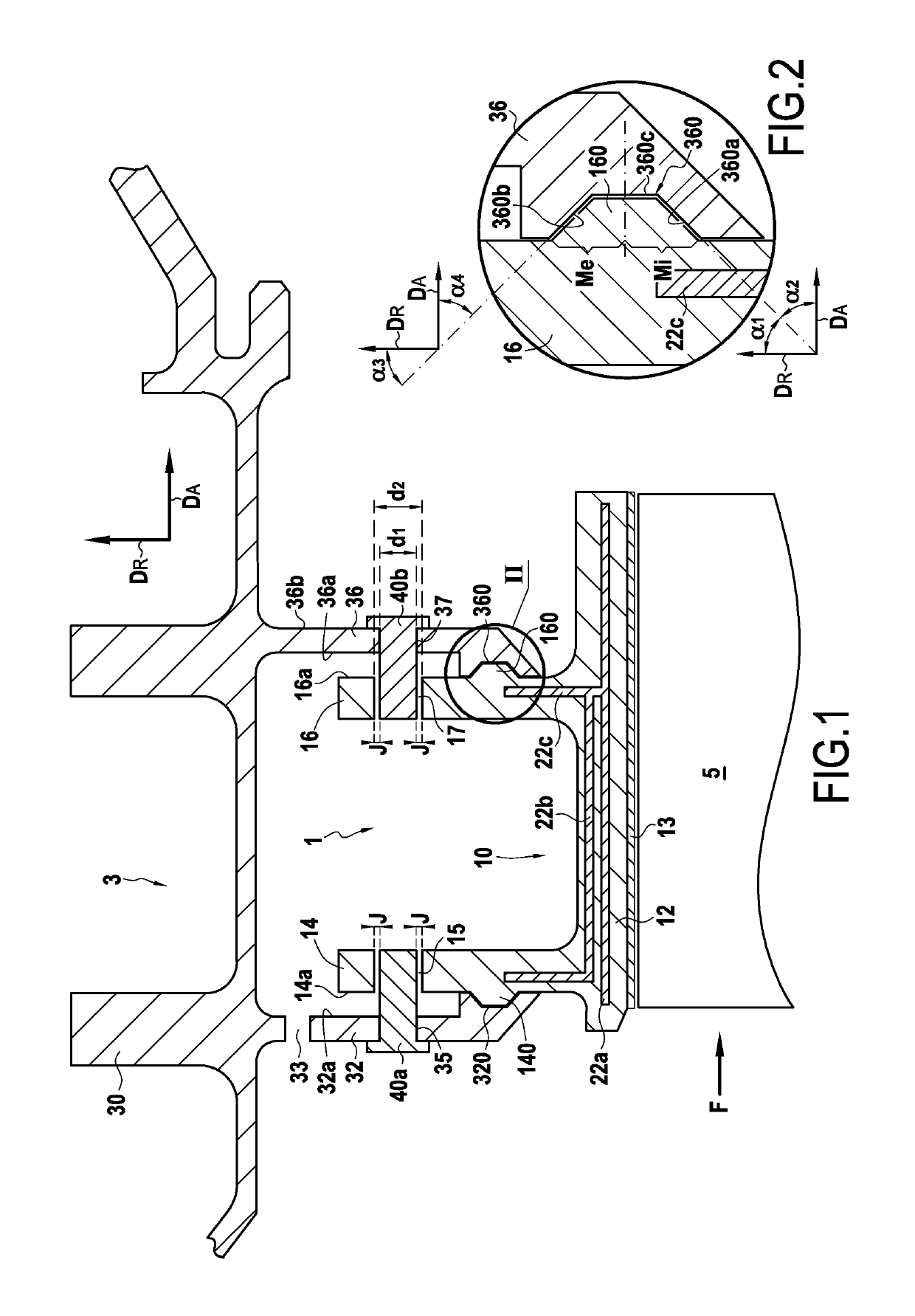
[0028]FIG. 1 shows a high pressure turbine ring assembly comprising a turbine ring 1 made of ceramic matrix composite (CMC) material and a metal ring support structure 3. The turbine ring 1 surrounds a set of rotary blades 5. The turbine ring 1 is made up of a plurality of ring sectors 10, FIG. 1 being a radial section view on a plane passing between two consecutive ring sectors. The ring sectors 10 in the example shown are Pi-shaped in axial section. Arrow DA shows the axial direction relative to the turbine ring 1, while arrow DR shows the radial direction relative to the turbine ring 1.

[0029]Each ring sector 10 is of cross-section that is substantially in the shape of an upside-down Greek letter π with an annular base 12 having its inner face coated in a layer 13 of abradable material that defines the flow passage for the gas stream through the turbine. Upstream and downstream tabs 14 and 16 extend from the outer face of the annular base 12 in the radial direction DR. The terms “...


PUM


Abstract

A turbine ring assembly includes ring sectors forming a turbine ring, and a ring support structure having two annular flanges, each ring sector having a portion forming an annular base with an inner face defining the inside face of the turbine ring and an outer face from which there project at least two tabs, the tabs being retained between the two annular flanges. Each tab of the ring sectors includes a projecting portion on its face situated facing one of the two annular flanges, this projecting portion co-operating with a housing present in the annular flange. Each tab of the ring sectors includes an opening in which there is received a portion of a retention element secured to the annular flange situated facing the tab. The retention element is made of a material having a thermal expansion coefficient that is greater than that of the material of the ring sectors.

Description

CROSS REFERENCE TO RELATED APPLICATIONS[0001]This application is the U.S. National Stage of PCT / FR2016 / 053395 filed Dec. 14, 2016, which in turn claims priority to French Application No. 1562741, filed Dec. 18, 2015. The contents of both applications are incorporated herein by reference in their entirety.BACKGROUND OF THE INVENTION[0002]The field of application of the invention is particularly that of gas turbine aeroengines. Nevertheless, the invention is applicable to other turbine engines, e.g. industrial turbines.[0003]Ceramic matrix composite (CMC) materials are known for conserving their mechanical properties at high temperatures, which makes them suitable for constituting hot structural elements.[0004]For turbine ring assemblies that are made entirely out of metal, it is necessary to cool all of the elements of the assembly, and in particular the turbine ring, which is subjected to particularly hot streams. Such cooling has a significant impact on the performance of the engin...

Claims


Application Information

Patent Timeline
Patent Type & Authority Patents(United States)
IPC IPC(8): F01D11/02F01D25/24F01D11/18
CPCF01D25/246F01D11/025F01D11/18F05D2300/6033F05D2230/644F05D2240/11F05D2230/642
Inventor ROUSSILLE, CLÉMENTTESSON, THIERRY
Owner SN DETUDE & DE CONSTR DE MOTEURS DAVIATION S N E C M A
Why Eureka
Try Eureka