
Suspension member for vehicle

a suspension member and vehicle technology, applied in the field of suspension members, can solve the problems of difficult to enhance the rigidity efficiently, increase in mass, and difficult to enhance the rigidity through the entire suspension member in well balance, so as to enhance the torsional rigidity of the base portion enhance the bending rigidity of the body part, and enhance the torsional rigidity of each coupling portion

Inactive Publication Date: 2019-08-13
TOYOTA JIDOSHA KK
View PDF25 Cites 4 Cited by
  • Summary
  • Abstract
  • Description
  • Claims
  • Application Information

AI Technical Summary

Benefits of technology

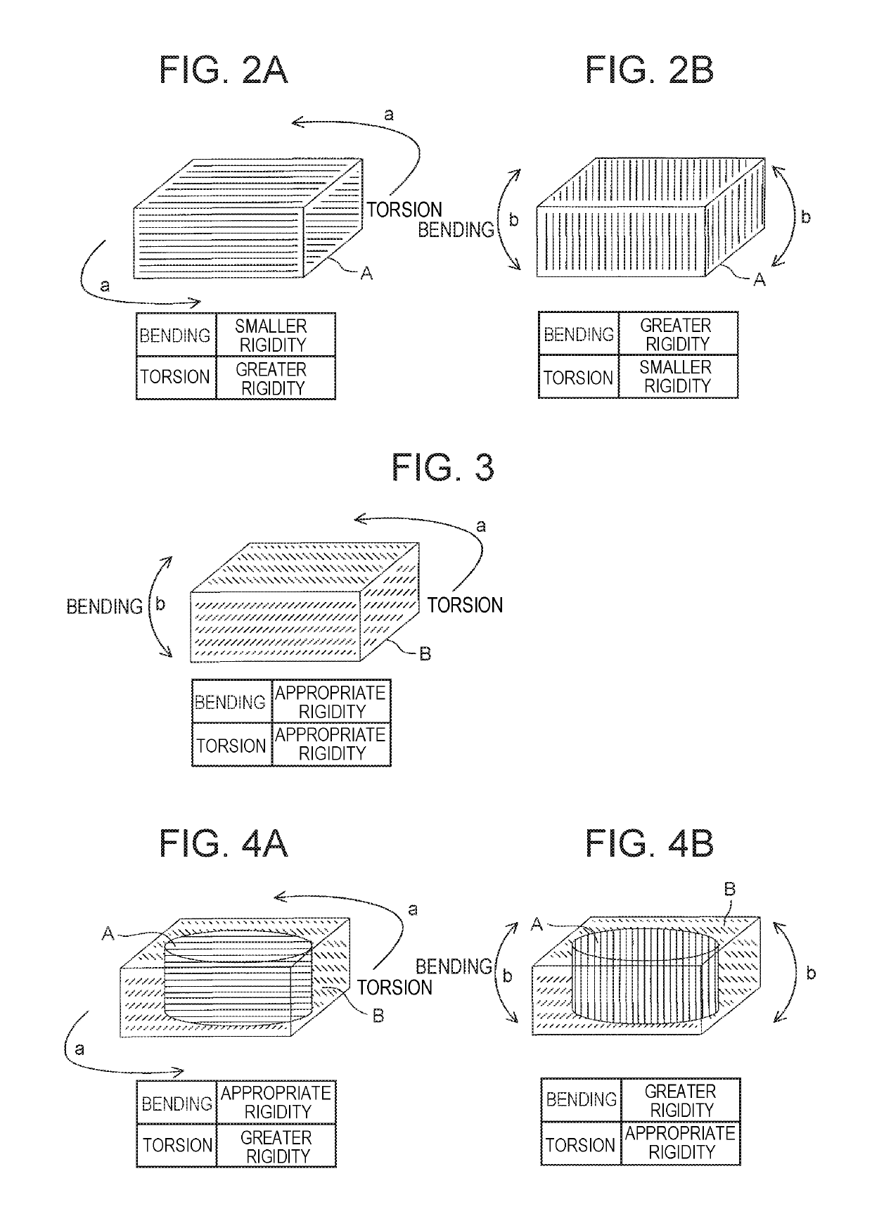
The present invention provides a way to make a vehicle's suspension member rigid without adding extra weight. This is achieved by using a special material called unidirectional carbon-fiber composite, which is placed in certain parts of the suspension member to enhance its rigidity against torsional loads. By orienting the carbon fibers in a different direction than the bending loads on the body of the vehicle, the torsional rigidity of each coupling portion is enhanced, ensuring overall rigidity of the entire suspension member.

Problems solved by technology

Hence, it is difficult to efficiently enhance the rigidity by the sectional shape of the knuckle 100, and increase in mass is likely to be caused.
Consequently, even if the technique proposed in WO 2012 / 137554 A is applied, it is difficult to enhance the rigidity through the entire suspension member in well balance.
However, great partial loads act on the suspension member.

Method used


Image

  • Suspension member for vehicle
  • Suspension member for vehicle
  • Suspension member for vehicle

Examples


first embodiment

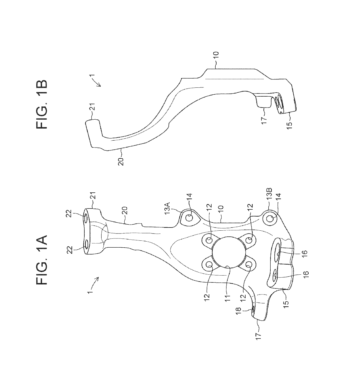
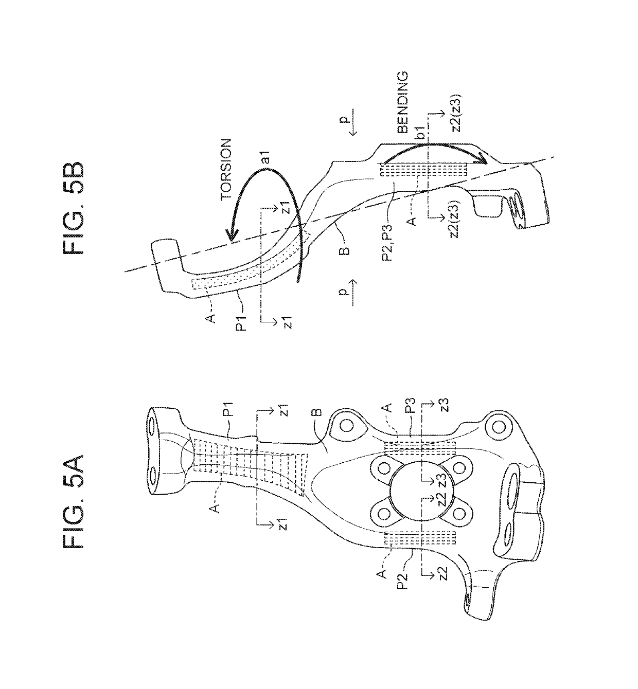
[0061]Even if the knuckle 1 as the aforementioned suspension member of the first embodiment has multiple particular portions whose rigidities are required to be enhanced, and directions in which the rigidities are desired to be enhanced are different from one another, the unidirectional carbon-fiber composite material A is embedded in these particular portions such that continuous fibers thereof are orientated in consideration of the respective directions in which the rigidities of these particular portions are desired to be enhanced. Accordingly, the rigidity can be enhanced in well balance through the entire knuckle 1. It is unnecessary to secure the rigidity by a sectional shape of the knuckle 1 made of a metallic material, as it is necessary in the related art; therefore, it is possible to attain reduction in space and reduction in weight. Accordingly, freedom of designing is promoted.

[0062]The second embodiment will be described, hereinafter. A suspension member for a vehicle o...

second embodiment

[0074]Even if the carrier 50 as the aforementioned suspension member of the second embodiment has the multiple particular portions whose rigidities are required to be enhanced and directions in which the rigidities are desired to be enhanced are different from one another, the unidirectional carbon-fiber composite material A is embedded in these particular portions such that the continuous fibers thereof are orientated in consideration of the respective directions in which the rigidities of these particular portions are desired to be enhanced. Accordingly, the rigidity can be enhanced in a well balance through the entire carrier 50. It is unnecessary to secure the rigidity by a sectional shape of a metallic material, as it is necessary in the related art; therefore, it is possible to attain reduction in space and reduction in weight. Accordingly, freedom of designing is promoted.

[0075]As aforementioned, the respective suspension members for a vehicle of the two embodiments have been...


PUM

PropertyMeasurementUnit
lengthaaaaaaaaaa
rigidityaaaaaaaaaa
torsional rigidityaaaaaaaaaa

Abstract

An overall knuckle is formed by a second carbon-fiber composite material, and a first carbon-fiber composite material is embedded in particular portions, whose rigidities are insufficient only with the second carbon-fiber composite material. The one particular portion is provided to a neck part, and the first carbon-fiber composite material is embedded in this particular portion such that continuous fibers thereof are orientated in a direction orthogonal to a central axis of a torsional load so as to enhance a torsional rigidity. The other particular portions are provided to the body part, and the first carbon-fiber composite material is embedded in these particular portions such that the continuous fibers thereof are orientated in a vertical direction so as to enhance a bending rigidity.

Description

INCORPORATION BY REFERENCE[0001]The disclosure of Japanese Patent Application No. 2016-009430 filed on Jan. 21, 2016 including the specification, drawings and abstract is incorporated herein by reference in its entirety.BACKGROUND[0002]1. Technical Field[0003]The present disclosure relates to a suspension member for a vehicle used in a suspension that suspends a wheel relative to a vehicle body.[0004]2. Description of Related Art[0005]A suspension member for a vehicle is provided between a wheel and a vehicle body, and thus various loads, such as a load inputted from a road surface via the wheel, a load inputted from the vehicle body, and a load inputted from a steering mechanism, act on this suspension member. Hence, the suspension member is required to have an appropriate rigidity against such loads. For example, as an example of such a suspension member, there has been known a front knuckle (hereinafter, referred to as a knuckle). FIG. 9A is a front view of a knuckle 100, and FIG...

Claims


Application Information

Patent Timeline
Patent Type & Authority Patents(United States)
IPC IPC(8): B62D7/18B29C70/08B29C65/00B29K307/04
CPCB62D7/18B29C66/72141B29C70/081B60Y2304/03B60G2206/013B60G2206/50B60G2206/7101B29K2307/04B60G7/00B60G2204/43B60G2206/71
Inventor SAKUMA, HITOSHI
Owner TOYOTA JIDOSHA KK
Learn More