
Golf club

Active Publication Date: 2022-08-09
PRGR CO LTD
View PDF23 Cites 0 Cited by
  • Summary
  • Abstract
  • Description
  • Claims
  • Application Information

AI Technical Summary

Benefits of technology

The present technology provides a golf club that reduces torsion when hitting a ball and increases durability without adding much weight to the club. It achieves this by using bias layers to reduce torsion and straight layers to increase strength and durability.

Problems solved by technology

In such a golf club, every time a ball is struck, a large impact load is applied to the portion of the shaft corresponding to the upper end of the cylindrical portion, so a portion of the shaft can become damaged.
Also, the load applied to the shaft in the torsional direction when hitting a ball has not particularly been taken into consideration.

Method used


Image

  • Golf club
  • Golf club
  • Golf club

Examples


experiment example 8

[0107 satisfied all of claims 1 to 4 of the present technology.

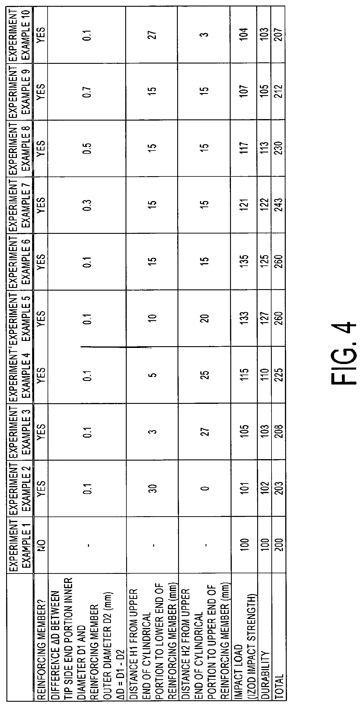
[0108]In Experiment Example 8, the difference ΔD was set to 0.5 mm, which is on the upper limit of the range 0.1 mm≤ΔD≤0.5 mm.

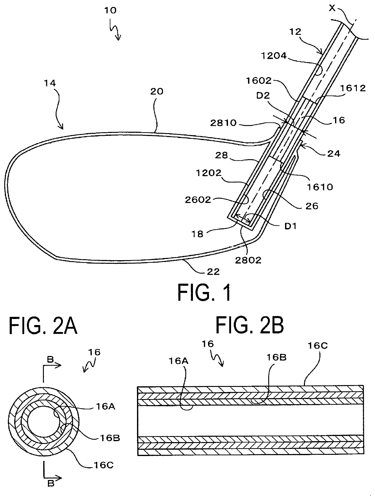
[0109]Also, in Experiment Example 8, the lower end 1610 of the reinforcing member 16 was located at a position 15 mm below the upper end 2810 of the cylindrical portion 28, which was within the range from 5 mm to 30 mm.

[0110]Also, the upper end 1612 of the reinforcing member 16 was located at a position 15 mm above the upper end 2810 of the cylindrical portion 28, which was within the range from 5 mm to 30 mm.

[0111]Therefore, with an index value of 117 for impact load and 113 for durability and a total score of 230, the evaluation was higher compared with Experiment Examples 1 and 2, but the evaluation was lower compared with Experiment Examples 6 and 7. This is because the difference ΔD was larger than that for Experiment Examples 6 and 7.

[0112]Experiment Example 9 satisfied claims 1, 3, and 4 of...


PUM


Abstract

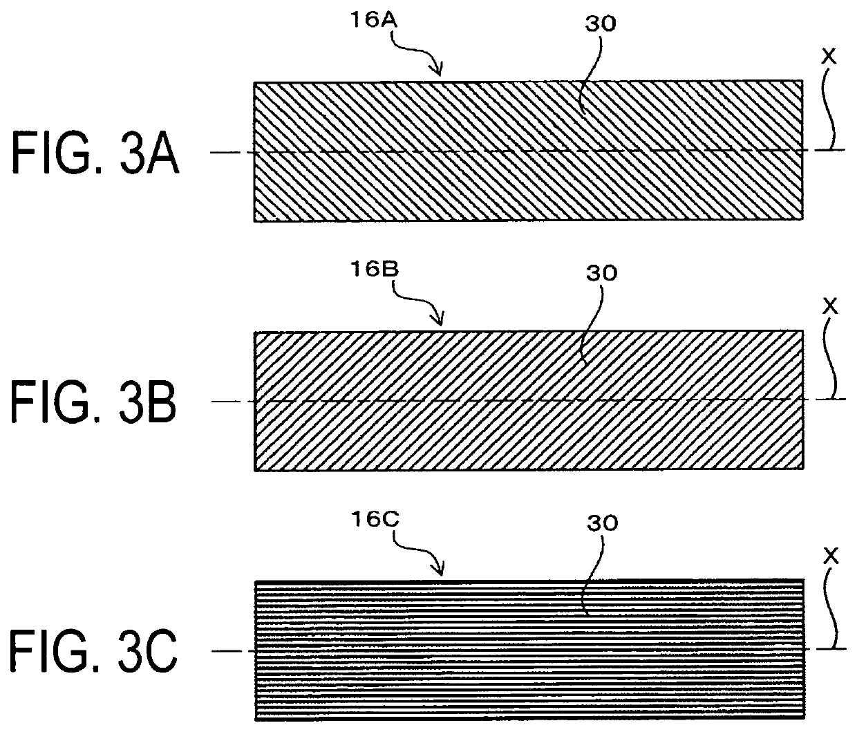
A golf club includes a reinforcing member installed on an inner circumferential surface of a shaft near a tip-side end portion and extends in an axial direction of the shaft to straddle an upper end of a cylindrical portion. The reinforcing member has a cylindrical shape configured by laminating prepregs obtained by impregnating carbon fibers being reinforcing fibers with a matrix resin. The reinforcing member is provided with: a first bias layer located at the innermost side in a radial direction; a second bias layer laminated on an outer side of the first bias layer (16A) in the radial direction, an orientation direction of the reinforcing fibers having an opposite direction to the first bias layer; and a straight layer laminated on the outer side of the second bias layer in the radial direction, an orientation direction of the reinforcing fibers being parallel to the axial direction of the shaft.

Description

TECHNICAL FIELD[0001]The present technology relates to a golf club.BACKGROUND ART[0002]Golf clubs are provided that include a hollow shaft, and a golf club head having a hosel portion into which a tip side end portion of the shaft is inserted and fixed.[0003]The hosel portion projects to the inside and outside of the golf club head, and has a cylindrical portion provided with a shaft installation hole into which the tip side end portion is inserted.[0004]In such a golf club, every time a ball is struck, a large impact load is applied to the portion of the shaft corresponding to the upper end of the cylindrical portion, so a portion of the shaft can become damaged.[0005]Therefore, in Japanese Unexamined Patent Publication No. 2014-233303, technology for reinforcing the shaft while minimizing the increase in mass is disclosed in which a solid reinforcing rod is installed on the inner circumferential surface of the tip side end portion of the shaft extending in the axial direction of t...

Claims


Application Information

Patent Timeline
IPC IPC(8): A63B53/02A63B53/12A63B53/04
CPCA63B53/02A63B53/12A63B53/0466A63B2209/02A63B60/00A63B2209/023
Inventor KITAZAKI, TSUYOSHIKOGAWA, MASAYOSHINISHIZAWA, YOHNAKAHARA, NORIHIKO
Owner PRGR CO LTD
Learn More