
Device and method for correcting seismic data for variable air-water interface

a technology of air-water interface and device, which is applied in seismology, seismology, instruments, etc., can solve the problems of not providing accurate, not adjusting, or adjusting, and affecting the accuracy of the final image of the subsurface,

Active Publication Date: 2019-07-09
CGG SERVICES SAS
View PDF10 Cites 1 Cited by
  • Summary
  • Abstract
  • Description
  • Claims
  • Application Information

AI Technical Summary

Benefits of technology

The patent text describes a method to correct images of a surface caused by the reflection of seismic waves from water. This is done by calculating a special operator that takes into account the position of the seismic source and the interface between air and water. The recorded seismic data is then corrected based on this operator to produce transformed seismic data. This transformed data is then used to generate an image of the subsurface layers of the earth. The method is useful for improving seismic imaging of underground structures. The computer text also includes a computing device and a computer-readable medium for implementing the method.

Problems solved by technology

While this profile does not provide an accurate location for oil and gas, it suggests, to those trained in the field, the presence or absence of oil and / or gas.
In essence, interference between primary and ghost arrivals causes notches, or gaps, in the frequency content recorded by the detectors.
However, the ghosts disturb the accuracy of the final image of the subsurface and, for at least this reason, various methods exist for removing the ghosts, i.e., deghosting, from the results of a seismic analysis.
This affects the quality of further seismic processing and ultimately, the final image of the earth's reflectivity.
However, recording such low frequencies requires a modified acquisition set up, which is undesirable.
As above, this approach requires continuous measurements of wave height along the streamer, which is not easy to obtain.
However, all these methods require continuous measurements of the wave height along the streamer or a substantial modification of the acquisition set up or the use of an impulsive source, neither of which is desired.

Method used


Image

  • Device and method for correcting seismic data for variable air-water interface
  • Device and method for correcting seismic data for variable air-water interface
  • Device and method for correcting seismic data for variable air-water interface

Examples


Embodiment Construction

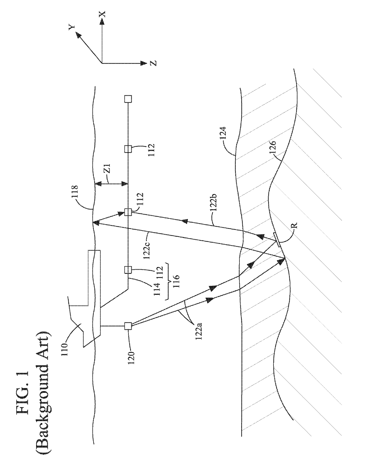
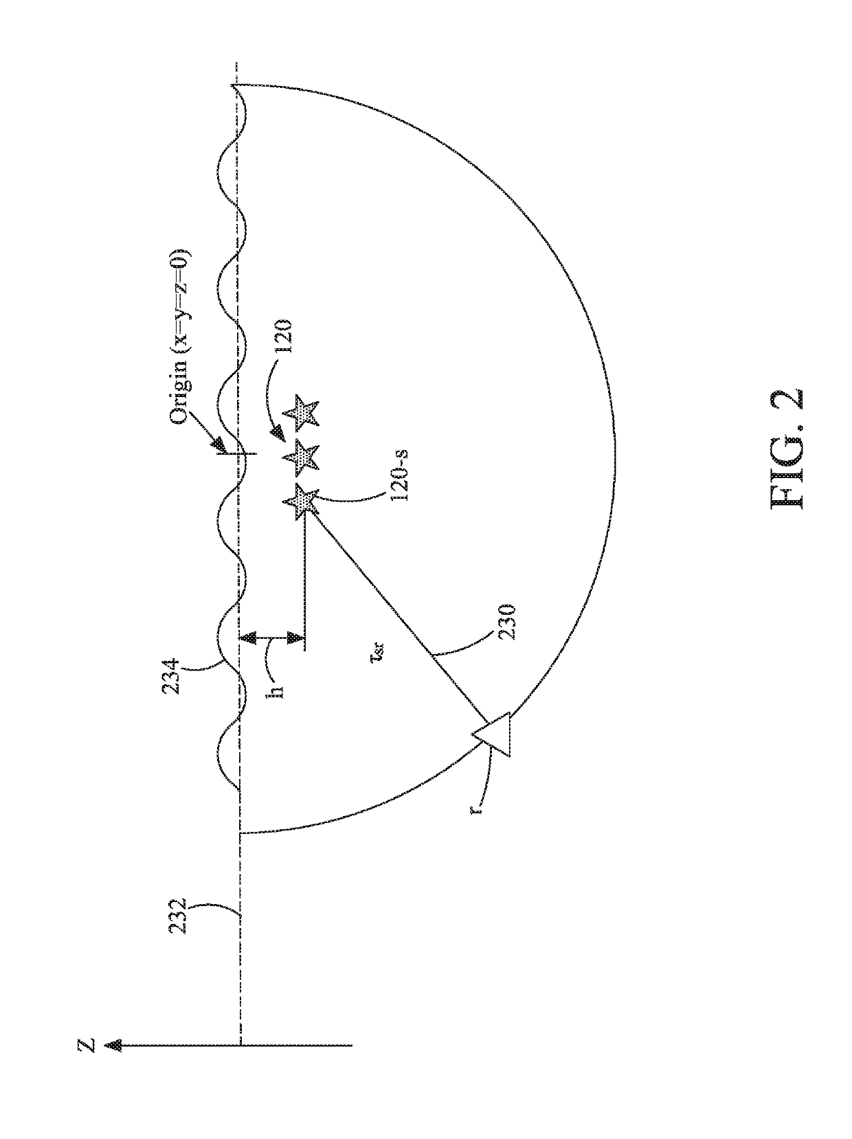
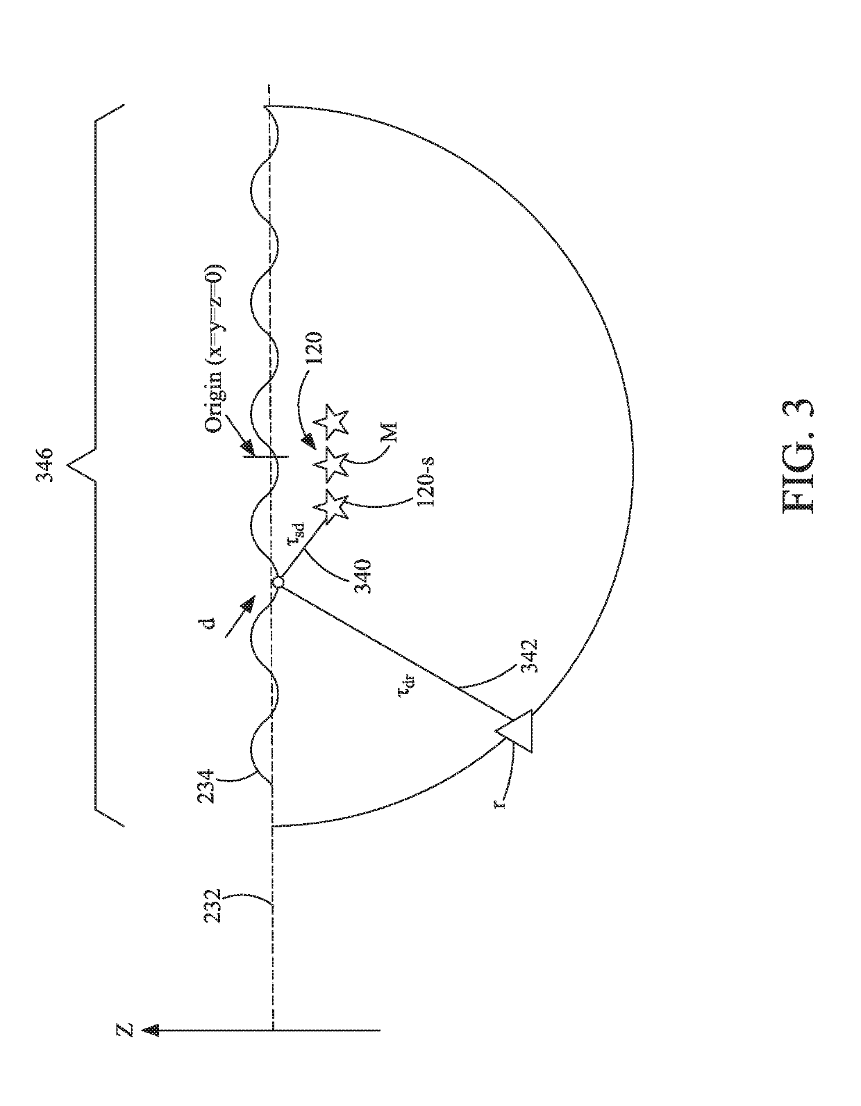
[0031]The following description of the exemplary embodiments refers to the accompanying drawings. The same reference numbers in different drawings identify the same or similar elements. The following detailed description does not limit the invention. Instead, the scope of the invention is defined by the appended claims. The following embodiments are discussed, for simplicity, with regard to a marine seismic acquisition system that generates seismic data using vibratory source elements. However, the embodiments to be discussed next are not limited to data generated by the vibratory sources, but they may be applied to data generated by impulsive sources that are grouped in an array and are fired in a “popcorn” manner, i.e., various air guns of the array are fired at various times so that a change in the air-water interface impacts differently the energy emission of one source element relative to another in the array.

[0032]Reference throughout the specification to “one embodiment” or “...


PUM


Abstract

Computing device, computer instructions and method for correcting an image, of a surveyed surface, due to a free-surface reflection. The method includes calculating a free surface reflection operator for a seismic source displaced in water based on a position of the source, and an air-water interface datum; receiving recorded seismic data d recorded with seismic sensors (r), wherein the recorded seismic data is associated with a pressure and / or a particle motion produced by a seismic wave in earth; correcting the recorded seismic data d based on the free surface reflection operator to obtain transformed seismic data; and generating an image of the surveyed subsurface, based on the transformed seismic data, wherein the image is indicative of various layers of the earth. The free surface reflection operator varies while a source signal is being emitted by the source.

Description

CROSS-REFERENCE TO RELATED APPLICATIONS[0001]The present application claims the benefit of priority of U.S. Provisional Application 62 / 288,640, having the title “Method to correct for variable sea surface during non-impulsive emission,” filed on Jan. 29, 2016, the entire contents of which are incorporated herein by reference.BACKGROUND[0002]Technical Field[0003]Embodiments of the subject matter disclosed herein generally relate to methods and systems and, more particularly, to mechanisms and techniques for correcting seismic data, collected with one or more marine seismic sensors, and generating an improved image of the surveyed subsurface.[0004]Discussion of the Background[0005]Marine seismic data acquisition and processing generate a profile (image) of the geological structure (subsurface) under the seafloor. The image represents a geophysical parameter of the earth. While this profile does not provide an accurate location for oil and gas, it suggests, to those trained in the fiel...

Claims


Application Information

Patent Timeline
Patent Type & Authority Patents(United States)
IPC IPC(8): G01V1/36G01V1/30G01V1/28G01V1/38
CPCG01V1/36G01V1/282G01V1/301G01V1/38G01V1/364G01V2210/614G01V2210/532G01V2210/56
Inventor POOLE, GORDON
Owner CGG SERVICES SAS
Learn More