
System and method for improving LIDAR sensor signal availability on a wind turbine

a lidar sensor and wind turbine technology, applied in the field of wind turbines, can solve the problems of wind turbine shutdown, excessive turbine load and/or fatigue, partial blocking of lidar beam signals, etc., and achieve the effect of minimizing interference and improving the signal availability of laser sensors

Active Publication Date: 2019-07-02
GENERAL ELECTRIC CO
View PDF9 Cites 2 Cited by
  • Summary
  • Abstract
  • Description
  • Claims
  • Application Information

AI Technical Summary

Benefits of technology

The present patent is about improving the signal availability of a laser sensor or LIDAR sensor mounted on a wind turbine. The technical effects of the patent are reducing interference between the laser signals and the rotor blades, minimizing the impact of the rotor position on the laser signals, and optimizing the mounting location and geometry of the laser signals to minimize interference. The system includes a laser sensor and a controller that coordinates the rotor position with the laser signals to reduce interference during rotor rotation.

Problems solved by technology

As a result, the wind gust may cause rotor acceleration that will create excessive turbine loading and / or fatigue.
In some instances, the wind gust may cause the rotor speed or power output to exceed a trip limit, before a wind turbine operation adjustment is completed, causing the wind turbine to be shut down.
However, when LIDAR sensors are mounted on the nacelle, rotor rotation can result in partial blocking of the LIDAR beam signals.
Such control systems, however, substantially reduce the LIDAR signal availability and the quality of the wind field assessments of impinging wind vectors.

Method used


Image

  • System and method for improving LIDAR sensor signal availability on a wind turbine
  • System and method for improving LIDAR sensor signal availability on a wind turbine
  • System and method for improving LIDAR sensor signal availability on a wind turbine

Examples


Embodiment Construction

[0029]Reference now will be made in detail to embodiments of the invention, one or more examples of which are illustrated in the drawings. Each example is provided by way of explanation of the invention, not limitation of the invention. In fact, it will be apparent to those skilled in the art that various modifications and variations can be made in the present invention without departing from the scope or spirit of the invention. For instance, features illustrated or described as part of one embodiment can be used with another embodiment to yield a still further embodiment. Thus, it is intended that the present invention covers such modifications and variations as come within the scope of the appended claims and their equivalents.

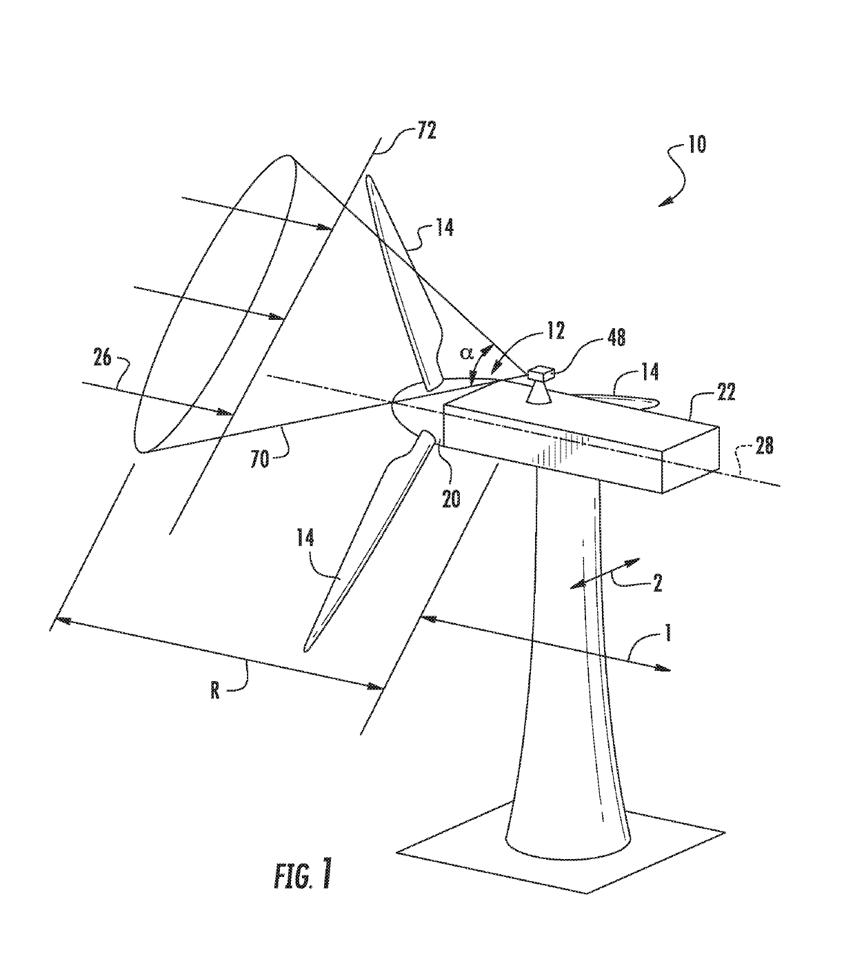
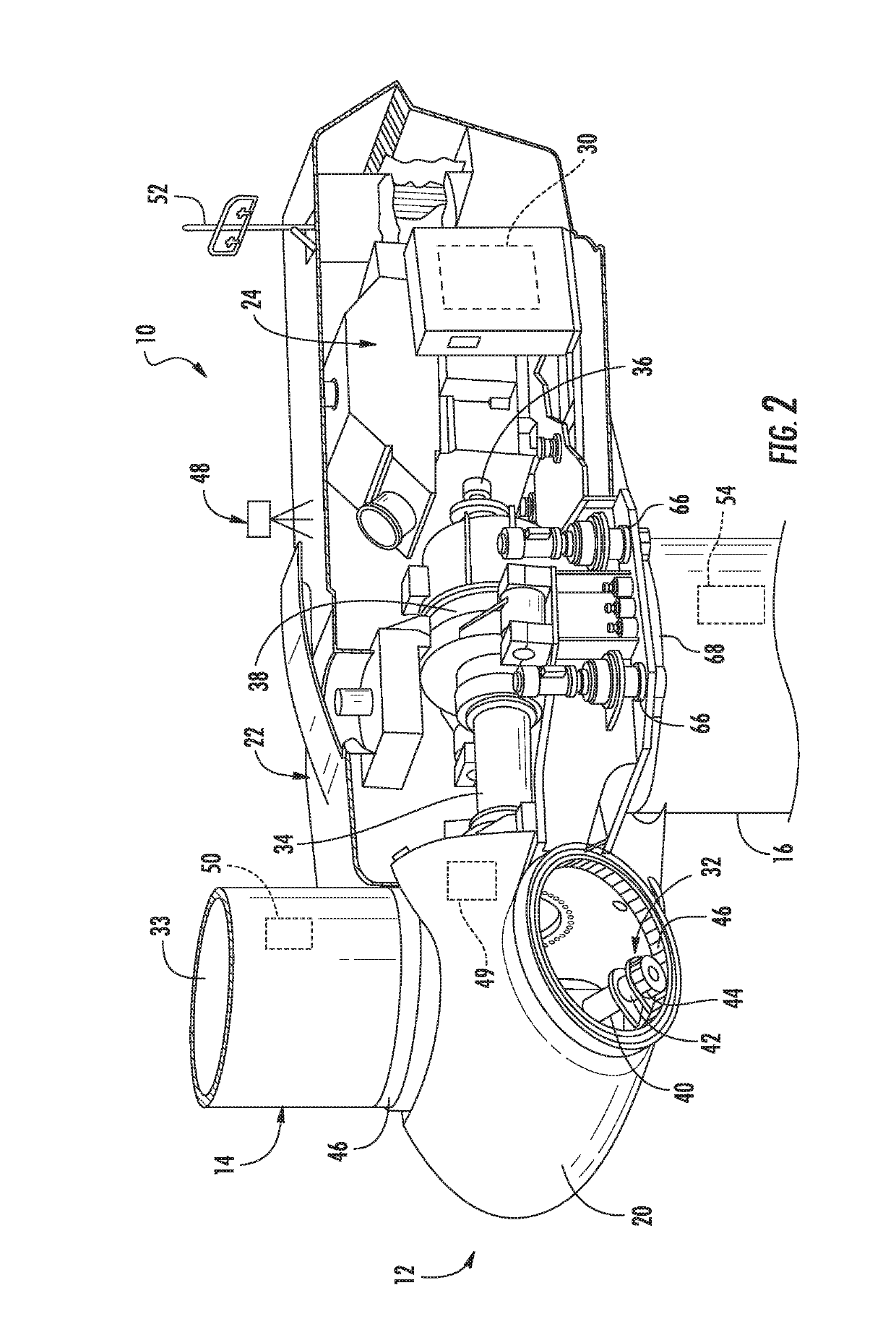
[0030]Generally, the present subject matter is directed to a system and method for sequencing Light Detecting and Ranging (LIDAR) sensor beam signals from a LIDAR sensor mounted on a nacelle of a wind turbine with the rotor position of the wind turbine so a...


PUM


Abstract

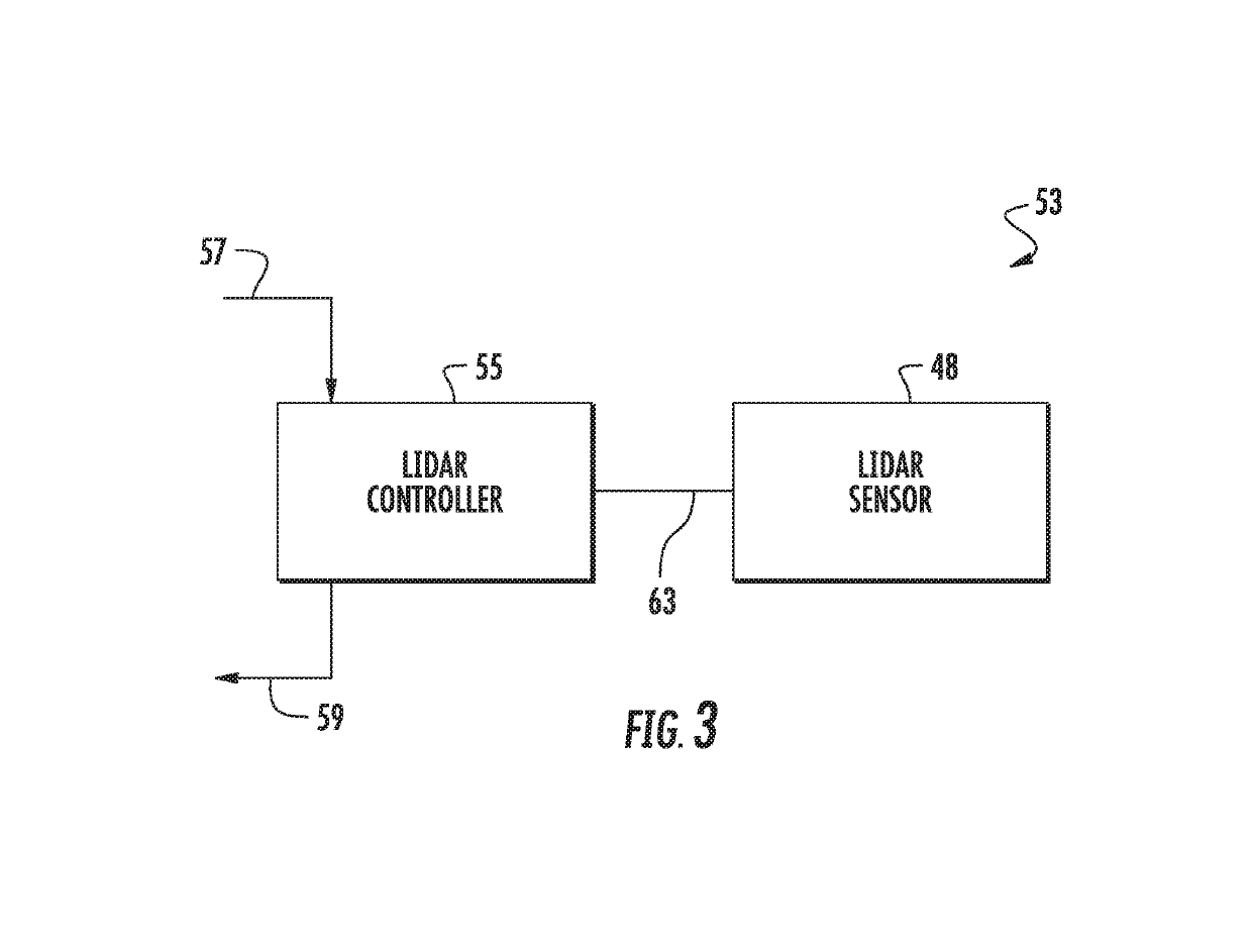
The present subject matter is directed to a system and method for sequencing Light Detecting and Ranging (LIDAR) sensor beam signals from a LIDAR sensor mounted on a nacelle of a wind turbine with the rotor position of the wind turbine so as to improve signal availability. More specifically, the method includes generating, via the LIDAR sensor, one or more laser signals towards the rotor of the wind turbine, the rotor having one or more rotor blades. The method also includes receiving, via a controller, a rotor position of the rotor of the wind turbine. Thus, the method further includes coordinating, via a control algorithm programmed within the controller, the rotor position with the one or more laser signals of the laser sensor so as to minimize interference between the laser signal(s) and the rotor blades during rotation of the rotor.

Description

FIELD OF THE INVENTION[0001]The present invention relates generally to wind turbines, and more particularly, to systems and methods for sequencing Light Detecting and Ranging (LIDAR) sensor beam signals with the rotor position of a wind turbine so as to improve signal availability.BACKGROUND OF THE INVENTION[0002]Wind power is considered one of the cleanest, most environmentally friendly energy sources presently available, and wind turbines have gained increased attention in this regard. A modern wind turbine typically includes a tower, a generator, a gearbox, a nacelle, and a rotor. The rotor typically includes a rotatable hub having one or more rotor blades attached thereto. A pitch bearing is typically configured operably between the hub and the rotor blade to allow for rotation about a pitch axis. The rotor blades capture kinetic energy of wind using known airfoil principles. The rotor blades transmit the kinetic energy in the form of rotational energy so as to turn a shaft coup...

Claims


Application Information

Patent Timeline
Patent Type & Authority Patents(United States)
IPC IPC(8): F03D7/04G01P5/26F03D17/00G01S7/497F03D1/06G01S7/481G01S17/95G01S17/58
CPCG01S7/4972F03D1/0675F03D17/00G01S7/4818G01S7/497G01S17/58G01S17/95Y02E10/726F05B2240/221F05B2260/83F05B2270/8042Y02A90/19Y02E10/721Y02A90/10Y02E10/72
Inventor MASHTARE, DALE ROBERTDRAPER, SAMUEL DAVIDMARKHAM, THOMAS STEPHENSHANE, CONNER B.STINSON, KATHERINE DERKSEN
Owner GENERAL ELECTRIC CO
Learn More