
Method and system for energy conversion from a flow of fluid

a technology of energy conversion and fluid flow, applied in the direction of wind energy generation, mechanical equipment, machines/engines, etc., can solve the problems of limited number of locations available for harvesting renewable energy, limited amount of energy available, and run out of fossil fuels, etc., to facilitate easy movement of the base station and facilitate the handling of the conductor

Active Publication Date: 2019-07-02
SEAQURRENT HLDG BV
View PDF22 Cites 2 Cited by
  • Summary
  • Abstract
  • Description
  • Claims
  • Application Information

AI Technical Summary

Benefits of technology

The invention aims to offer a better option to existing energy conversion systems, making them more efficient, easy to control and maintain. The technical effects of the patent include improved energy conversion and more efficient use of energy.

Problems solved by technology

Besides the problem that we will run out of fossil fuels at a certain moment, investigations show that combustion of fossil fuels contributes significantly to air pollution and the production of greenhouse gas.
Even though renewable energy has been recognized as a resource for global energy demand, due to the nature of renewable energy, there are a number of issues to tackle.
One of them is that the amount of energy available is restricted.
Furthermore the number of locations available for harvesting renewable energy is limited.
An additional challenge is that the price of renewable energy has to be at such a level that a transition from conventional energy to renewable energy can be borne by the market.
Wave-induced eddies at the sea surface and eddies created by the seabed have a significant effect on the velocity profile of tidal currents causing practical problems for converting energy from these types of moving water bodies.
The control of this known system is complex and due to the long control cables the system is difficult to control.
Due to the requirement to reel them in and out the cables are subjected to extensive tear and wear which is introducing frequently inspection and maintenance activities.
Furthermore, due to the inability of this known system to make short radius turns, the system is operated with a digit eight or an oval shaped trajectory resulting in a large energy leakage.
Also, due to controlling the airfoil kites in tandem, it is not possible to adjust the angle-of-attack of each airfoil kite individually.
This is disadvantageous as, due to the long string of kites, the apparent direction of flow experienced by the individual kites is different to each other.
Besides that next to the aforementioned system other types of systems are known that are able to convert energy, all the known systems suffer from a number of disadvantages:a) The known systems have a low conversion rate and as a result the majority of the available energy remains untouched.
It goes without saying that the cost of developing such a row of systems is much higher than the installation of a single system that is able to convert the available energy in one go.b) The known systems suffer furthermore from a low efficiency caused by significant losses during conversion and transfer of the converted energy.
As the converted energy most of the time is consumed at a remote location, the losses during transfer of energy have a significant impact on the system performance.c) Components used in the known systems are subjected to extensive tear and wear and / or the systems have been designed such that inspection and maintenance is complex and expensive.

Method used


Image

  • Method and system for energy conversion from a flow of fluid
  • Method and system for energy conversion from a flow of fluid
  • Method and system for energy conversion from a flow of fluid

Examples


Embodiment Construction

[0057]In the following description, Z defines a horizontal flow of fluid direction, X a horizontal direction perpendicular to the flow of fluid direction and Y defines a vertical direction perpendicular to the flow of fluid direction.

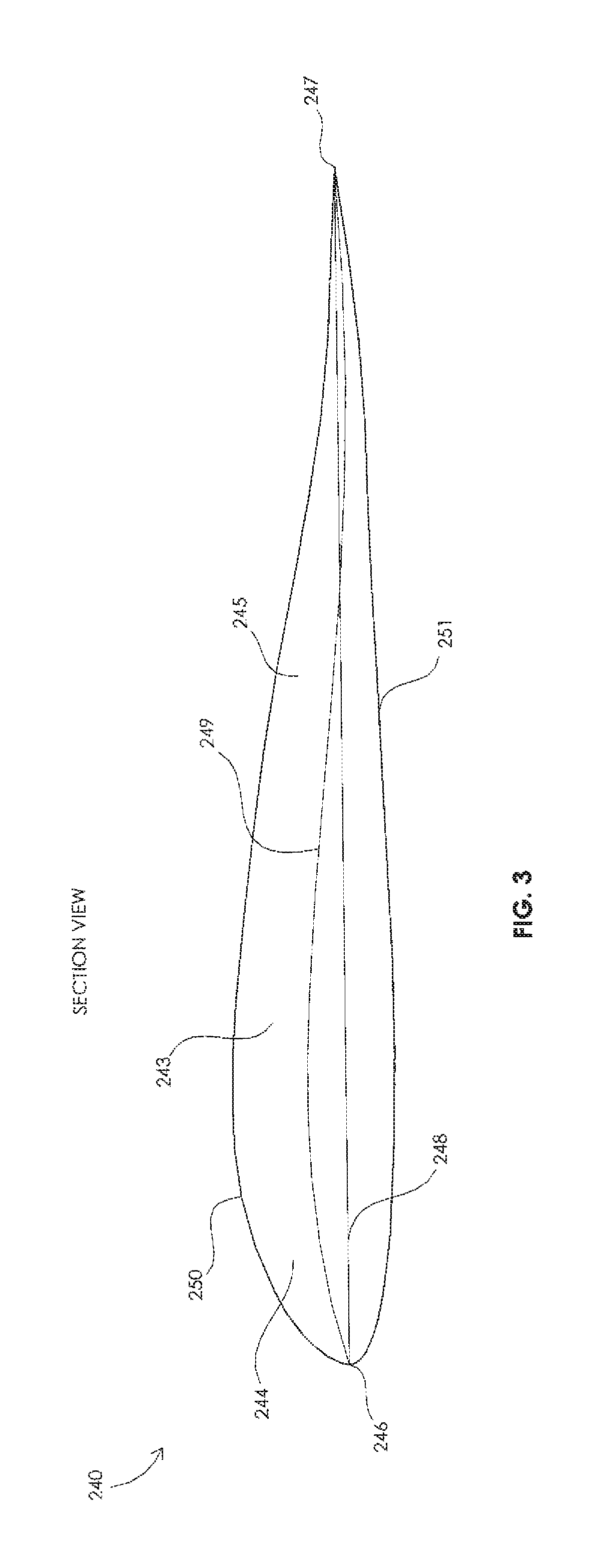
[0058]FIG. 1 shows a system denoted with reference 1 which is used to convert energy from the flow 50 of fluid into transportable energy. The system 1 comprises a fluid driven device 200 connected to a tether 300 wherein the tether 300 is coupled with a base station 400. The base station 400 is attached or attachable to a mooring 480 that is located at a bottom of a sea, river, lake, etc.

[0059]Preferably the base station 400 is provided with a transformation device 410 comprising at least one hydraulic cylinder. In connection therewith the tether 300 is preferably connected to a piston 412 that is movable in the hydraulic cylinder so that movement of the piston 412 causes hydraulic fluid to be displaced in a hydraulic system of which the hydraulic cylin...


PUM


Abstract

System for power generation from a flow of fluid, comprising a fluid driven device connected to a tether wherein the tether is coupled with a base station to convert energy from the flow of fluid into transportable energy, wherein the fluid driven device comprises a frame provided with adjustable vanes, and wherein the vanes are adjustable for setting into a predefine position relative to the flow of fluid. The fluid driven device comprises a working mode and a retraction mode, wherein in the working mode the vanes are set in a first predetermined position to generate a lift force from the flow of fluid, and wherein in the retraction mode the vanes are set in a second predetermined position to provide a low drag level to the flow of fluid, and wherein the work performed during working mode is larger than the work supplied during retraction mode.

Description

RELATED APPLICATIONS[0001]This application is a National Phase of PCT Patent Application No. PCT / NL2016 / 050353 having International filing date of May 18, 2016, which claims the benefit of priority of Netherlands Patent Applications Nos. 2014816 filed on May 18, 2015, and U.S. Pat. No. 2,014,817 filed on May 18, 2015. The contents of the above applications are all incorporated by reference as if fully set forth herein in their entirety.FIELD AND BACKGROUND OF THE INVENTION[0002]The invention relates to a system for energy conversion from a flow of fluid into transportable energy, comprising a fluid driven device connected to a tether wherein the tether is coupled with a base station.[0003]Energy demand for human consumption has significantly increased over the last decades and it has been forecasted that, due to growth of the world population, energy demand will further grow. Energy, according to the definition of physicists, can neither be created nor consumed or destroyed. However...

Claims


Application Information

Patent Timeline
Patent Type & Authority Patents(United States)
IPC IPC(8): F03B13/00F03B15/02F03B13/26F03B17/06F03D5/00F03B13/10
CPCF03B15/02F03B13/264F03B17/06F03D5/00F03B13/10Y02E60/17F05B2240/917F05B2240/921F05B2240/922F05B2240/97F05B2260/406F05B2260/507Y02E10/28Y02E10/70Y02E10/728Y02E60/16Y02E10/30F05B2240/9172Y02E10/20
Inventor WENTZEL, YOURI
Owner SEAQURRENT HLDG BV
Learn More