
Alumina sintered body and base substrate for optical device

a technology of optical devices and base substrates, which is applied in the field of alumina sintered bodies and base substrates for optical devices, can solve the problems of insufficiently high degree of orientation, and achieve the effects of high in-line transmittance, high transparency, and high in-line transmittan

Active Publication Date: 2019-07-02
NGK INSULATORS LTD
View PDF13 Cites 0 Cited by
  • Summary
  • Abstract
  • Description
  • Claims
  • Application Information

AI Technical Summary

Benefits of technology

[0007]Accordingly, it is a main object of the present invention to provide an alumina sintered body including only a small number of pores and having high in-line transmittance.

Problems solved by technology

In NPL 1, however, a sufficiently high degree of orientation is not achieved unless a high magnetic field of 12 tesla is applied, and thus an alumina sintered body having an in-line transmittance of 60% or more is not produced.
An apparatus with which slip casting is performed while such a high magnetic field is applied is currently installed only in a limited number of facilities.

Method used


Image

  • Alumina sintered body and base substrate for optical device
  • Alumina sintered body and base substrate for optical device
  • Alumina sintered body and base substrate for optical device

Examples


experimental example 1

1. Production of Alumina Sintered Body

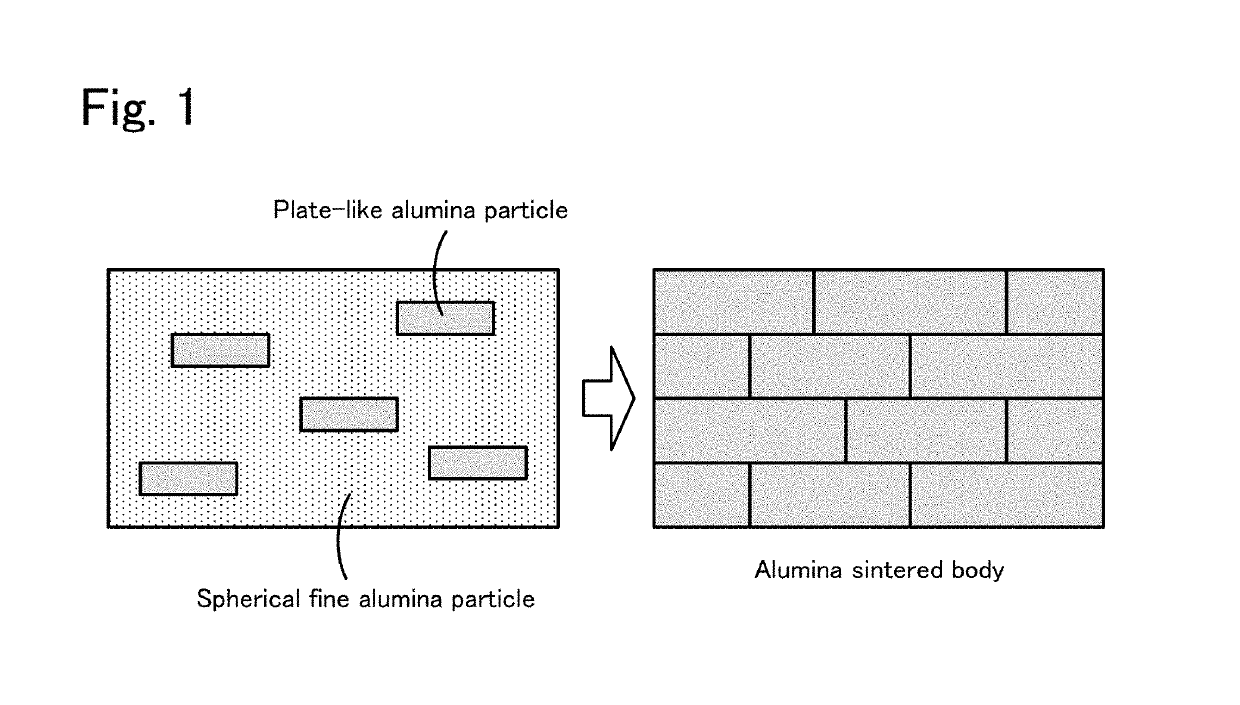
(1) Preparation of Plate-like Alumina Powder

[0037]In a pot mill, 96 parts by mass of a high-purity γ-alumina powder (TM-300D, manufactured by TAIMEI CHEMICALS CO., LTD.), 4 parts by mass of a high-purity AlF3 powder (special grade, manufactured by KANTO CHEMICAL CO., INC.), and 0.17 parts by mass of a high-purity α-alumina powder (TM-DAR, manufactured by TAIMEI CHEMICALS CO., LTD., D50=1 μm) serving as a seed crystal were mixed with each other for 5 hours using IPA (isopropyl alcohol) as a solvent and ϕ2 mm alumina balls. After the mixing in the pot mill, the IPA was dried using an evaporator to obtain a mixed powder. Into a high-purity alumina sagger (volume 750 cm3) having a purity of 99.5 mass %, 300 g of the obtained mixed powder was inserted and a high-purity alumina lid having a purity of 99.5 mass % was put thereon. The mixed powder was heat-treated in an electric furnace with air flow at 900° C. for 3 hours. The air flow rate was 25000 c...

experimental example 2

[0066]An alumina sintered body was produced in the same manner as in Experimental Example 1, except that the sintering temperature in the sintering in 1. (3) was changed to 1900° C. in the production of the alumina sintered body. The properties in 2. (1) to (7) were also determined for the produced alumina sintered body. Table 1 shows the results.

experimental example 3

[0067]An alumina sintered body was produced in the same manner as in Experimental Example 1, except that 0.75 parts by mass of the plate-like alumina powder and 99.25 parts by mass of the fine alumina powder were mixed in the tape casting in 1. (2) and the sintering temperature in 1. (3) was changed to 1900° C. in the production of the alumina sintered body. The properties in 2. (1) to (7) were also determined for the produced alumina sintered body. Table 1 shows the results.


PUM

PropertyMeasurementUnit
aaaaaaaaaa
crystal grain sizeaaaaaaaaaa
diameteraaaaaaaaaa

Abstract

An alumina sintered body according to the present invention includes a surface having a degree of c-plane orientation of 5% or more, the degree of c-plane orientation being determined by a Lotgering method using an X-ray diffraction profile obtained through X-ray irradiation at 2θ=20° to 70°. The alumina sintered body contains Mg and F, a Mg / F mass ratio is 0.05 to 3500, and a Mg content is 30 to 3500 ppm by mass. The alumina sintered body has a crystal grain size of 15 to 200 μm. When a field of view of 370.0 μm long×372.0 μm wide is photographed with a 1000-fold magnification and the photograph is visually observed, a number of pores having a diameter of 0.2 to 0.6 μm is 250 or less.

Description

BACKGROUND OF THE INVENTION[0001]1. Field of the Invention[0002]The present invention relates to alumina sintered bodies and base substrates for optical devices.[0003]2. Description of the Related Art[0004]Transparent alumina sintered bodies have been known. For example, in NPL 1, an alumina suspension containing MgO is subjected to slip casting under a magnetic field and fired in a vacuum at 1850° C. for 5 hours to produce a transparent alumina sintered body with oriented grains. For example, an alumina sintered body produced under a magnetic field of 12 tesla has an in-line transmittance at 600 nm of 70.3% and a high degree of orientation of 97%. An alumina sintered body produced under a magnetic field of 8 tesla has an in-line transmittance at 600 nm of about 56% and a slightly high degree of orientation of 78%. Furthermore, the in-line transmittance and the degree of orientation decrease as the magnetic field strength decreases to 6 tesla and 4 tesla. The results conclude that t...

Claims


Application Information

Patent Timeline
Patent Type & Authority Patents(United States)
IPC IPC(8): C01F7/00C04B35/645C04B35/634C04B35/632C01F7/44G02B1/02G01N23/207C04B35/115C01F7/02C01F7/442
CPCC01F7/02C04B35/115C04B35/632C04B35/6342C04B35/645G01N23/207G02B1/02C01F7/442C04B2235/788C01P2002/60C01P2002/72C01P2004/03C01P2004/22C01P2004/54C01P2004/61C01P2006/14C01P2006/16C01P2006/60C01P2006/80C04B2235/322C04B2235/3206C04B2235/3217C04B2235/445C04B2235/5292C04B2235/5296C04B2235/5436C04B2235/5445C04B2235/604C04B2235/6025C04B2235/658C04B2235/6567C04B2235/72C04B2235/725C04B2235/786C04B2235/787C04B35/10C04B38/0051
Inventor MATSUSHIMA, KIYOSHIWATANABE, MORIMICHISATO, KEINANATAKI, TSUTOMU
Owner NGK INSULATORS LTD
Learn More