Optical devices and optical components
A technology for optical components and optical devices, which is applied in the directions of optical components, optics, measuring devices, etc., to achieve the effects of high sensitivity, high direct transmission, and high reflection and scattering.
- Summary
- Abstract
- Description
- Claims
- Application Information
AI Technical Summary
Problems solved by technology
Method used
Image
Examples
Embodiment approach 1
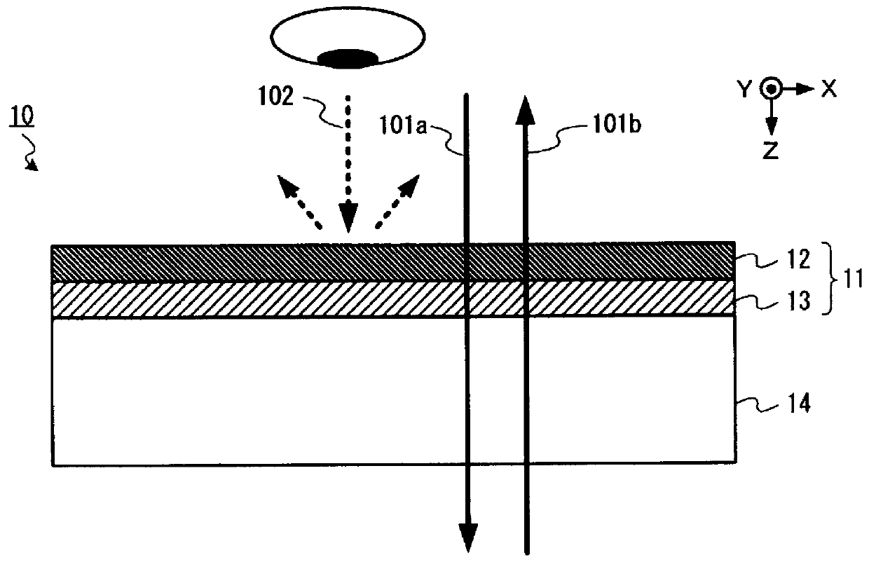
[0051] Embodiments of the present invention will be described with reference to the drawings. figure 1 It is a configuration diagram showing an example of the optical member 10 according to the first embodiment of the present invention. figure 1 The illustrated optical member 10 is used as an infrared light transmission filter that blocks visible light and transmits infrared light in an optical device or the like using infrared light. The optical member 10 transmits infrared light and reflects and scatters visible light, whereby the light-receiving region where visible light is observed is colored in a color other than black when viewed from at least the first side. It should be noted that the observed coloring is not limited to a single color, but also includes combinations of a plurality of colors such as mottled patterns and camouflage patterns. Here, the first side is the incident side or the exiting side of infrared light in the optical member 10 and a predetermined one si...
Embodiment approach 2
[0149] Next, a second embodiment of the present invention will be described with reference to the drawings. Figure 18 It is a configuration diagram showing an example of an optical device according to a second embodiment of the present invention.
[0150] Figure 18 The illustrated optical device 100 has an infrared light emitting unit 2 and / or an infrared light receiving unit 3 inside a housing 4 . Furthermore, in the optical device 100 , the optical member 1 is provided so as to cover the opening provided in the housing 4 . According to such a configuration, infrared light passes through the optical member 1 and is emitted to the outside of the housing 4 .
[0151] The optical device 100 is, for example, a camera device that captures an image using infrared light, a distance sensor that uses infrared light to detect the distance of an object or the presence or absence of a nearby object, a measurement device such as a proximity sensor, and a device that uses infrared ligh...
example 1
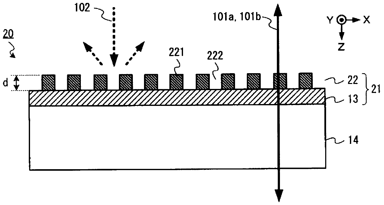
[0167] This example uses the figure 2 One embodiment of a diffractive structured optical member 20 is shown. First, a film composed of SiO 2 and Ta 2 o 5 A multilayer film having the structure shown in Table 2 below was constituted. It should be noted that the uppermost layer of SiO 2 The layer is formed as a layer to be a diffractive optical element described later.
[0168] [Table 2]
[0169] Table 2
[0170]
[0171] Figure 19 is a graph showing the transmittance characteristics of the multilayer film of this example. Such as Figure 19 As shown, the multilayer film of this example exhibits low transmittance for light in the visible region, and exhibits high transmittance characteristics for light with a wavelength of 900 nm or longer.
[0172] Next, on the first layer, which is the uppermost layer of the formed multilayer film, a range of ±74° in a certain direction and a range of ±49° in a direction perpendicular to it are formed at a wavelength of 915 nm. ...
PUM
| Property | Measurement | Unit |
|---|---|---|
| width | aaaaa | aaaaa |
| thickness | aaaaa | aaaaa |
| thickness | aaaaa | aaaaa |
Abstract
Description
Claims
Application Information
 - R&D
- Intellectual Property
- Life Sciences
- Materials
- Tech Scout
- Unparalleled Data Quality
- Higher Quality Content
- 60% Fewer Hallucinations
Browse by: Latest US Patents, China's latest patents, Technical Efficacy Thesaurus, Application Domain, Technology Topic, Popular Technical Reports.
© 2025 PatSnap. All rights reserved.Legal|Privacy policy|Modern Slavery Act Transparency Statement|Sitemap|About US| Contact US: help@patsnap.com


