
Structural body

a structure and body technology, applied in the field of structural bodies, can solve the problems of metal ions, such as silver ions, being liable to be transformed by light exposure, and achieve the effect of suppressing stress concentration and further suppressing the transformation of function layers

Active Publication Date: 2019-06-25
NGK INSULATORS LTD
View PDF27 Cites 0 Cited by
  • Summary
  • Abstract
  • Description
  • Claims
  • Application Information

AI Technical Summary

Benefits of technology

[0009]The present invention was made to solve the problem as described above, and a primary object of the present invention is to provide an easy handing structural body using a material which includes metal ions and which is transformed by light.
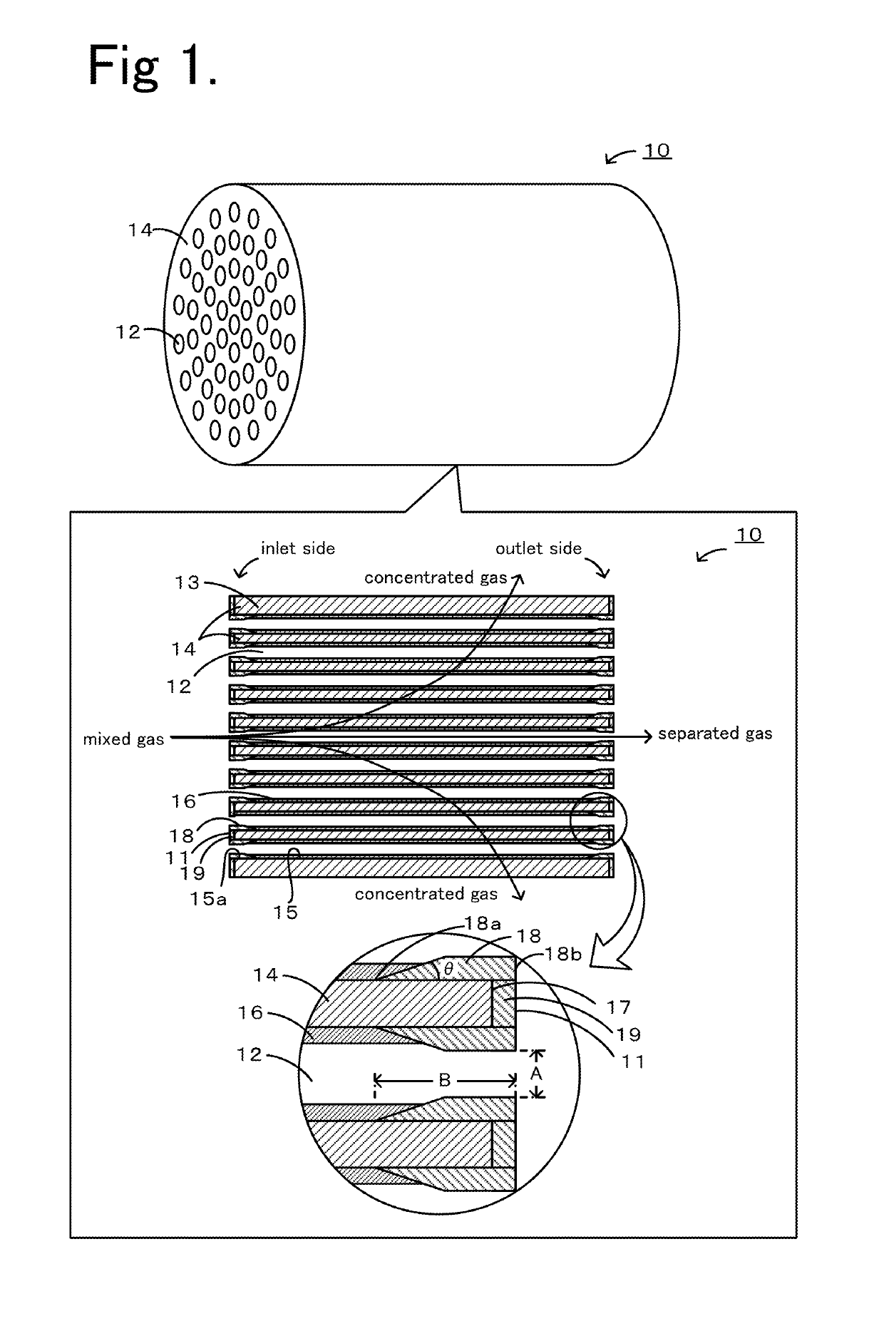
[0026]In the structural body of the present invention, the number of the cells may be at least two, and the standard deviation of the B / A among the above at least two cells may be set to 0.01 to 1.0. When the standard deviation is 0.01 or more, even if the structural body is exposed to a heat environment during production and use thereof, since the stress concentration can be suppressed, for example, at a boundary between the protective layer and the partition portion, so that cracks are not likely to be generated at the boundary as described above and the vicinity thereof (in particular, in the partition portion). In addition, when the standard deviation is 1.0 or less, since no cells having an excessively small B / A value are present, the function layer can be further suppressed from being transformed.

Problems solved by technology

However, since having low stability against light, metal ions, such as silver ions, are liable to be transformed by light exposure in some cases.

Method used


Image

  • Structural body
  • Structural body

Examples


examples

[0048]Hereinafter, examples in each of which the structural body 10 was concretely formed will be described as Experimental Examples. In addition, Experimental Examples 1 to 3, 5 to 9, 11 to 15, 17 and 18 correspond to the examples of the present invention, and Experimental Examples 4, 10, and 16 correspond to Comparative Examples.

experimental examples 1 to 18

1. Formation of Structural Body 10

(A) Formation of Partition Portion 14

(A-1) Formation of Coarse Particle Portion 14a

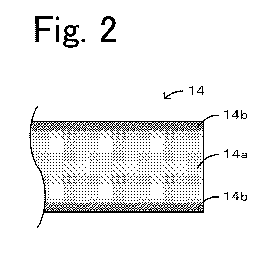
[0049]Alumina particles having an average particle diameter of 50 μm were used as an aggregate, and an organic binder and water were added to the above aggregate and then kneaded therewith, so that a paste was obtained. Next, by the use of a plunger-type extruder, the paste thus obtained was molded by extruding, so that a molded body having an outer diameter of 30 mm and a length of 160 mm and including cells each having a circular cross-section was obtained. Subsequently, the molded body thus obtained was dried at 100° C. for 24 hours using a hot wind circulation type drier and was then fired using an electric furnace, so that the coarse particle portion 14a was obtained. The firing conditions were set so that the temperature was 1,500° C., the firing time was 1 hour, and the temperature rise and drop rates were each 100° C. / hour.

(A-2) Application of Slurry for Form...


PUM

PropertyMeasurementUnit
thicknessaaaaaaaaaa
lengthaaaaaaaaaa
pore diameteraaaaaaaaaa

Abstract

A structural body 10 includes a porous partition portion 14 forming a plurality of cells 12 each of which is used as a flow path of a mixed gas as a fluid; a function layer 16 provided on each inside surface 15 of the partition portion 14; a protective layer 18 provided on each inside surface end portion 15a of the inside surface 15; and a sealing portion 19 provided on each end surface 17 of the partition portion 14. The function layer 16 contains metal ions, and is transformed by light. The protective layer 18 is a length B (mm) from an end surface 11 of the structural body 10 and a maximum length A (mm) of an opening of the cell 12 satisfy the relationship of B / A≥0.4.

Description

[0001]This application is a CON of PCT / JP2014 / 052318, filed Jan. 31, 2014.BACKGROUND OF THE INVENTION[0002]1. Field of the Invention[0003]The present invention relates to a structural body.[0004]2. Description of the Related Art[0005]Heretofore, various functions of metal ions have drawn attention and have been practically used. For example, an improvement in antibacterial / antimold properties of a total heat exchange element by the use of silver ions and / or zinc ions has been proposed (see PTL 1). In addition, there has been proposed separation of a paraffin, such as propane, and an olefin, such as propylene, by the use of a membrane formed by modifying a thin film having micropores or mesopores with silver ions (see NPL 1).CITATION LISTPatent Literature[0006]PTL 1: Japanese Unexamined Patent Application Publication No. 2009-189900 Non Patent Literature[0007]NPL 1: Microporous and Mesoporous Materials, 78 (2005) 235 to 243SUMMARY OF THE INVENTION[0008]However, since having low stabi...

Claims


Application Information

Patent Timeline
Patent Type & Authority Patents(United States)
IPC IPC(8): B01D46/24B01D63/06
CPCB01D46/247B01D63/066B01D46/2482B01D46/2498B01D46/2496
Inventor KINOSHITA, NAOTONODA, KENICHISHIBATA, HIROYUKI
Owner NGK INSULATORS LTD
Learn More