
Clear-to-send (CTS) power control in sidelink

a power control and sidelink technology, applied in power management, high-level techniques, mesh networks, etc., can solve problems such as ue-to-ue communications that may potentially interfere with enb-to-ue communications and/or other ue-to-ue communications

Active Publication Date: 2019-06-11
QUALCOMM INC
View PDF12 Cites 6 Cited by
  • Summary
  • Abstract
  • Description
  • Claims
  • Application Information

AI Technical Summary

Benefits of technology

This approach enhances communication efficiency and throughput by dynamically adjusting the interference protection zone, reducing interference and improving spatial reuse in wireless communication networks.

Problems solved by technology

In some circumstances, UE-to-UE communications may potentially interfere with eNB-to-UE communications and / or other UE-to-UE communications.

Method used


Image

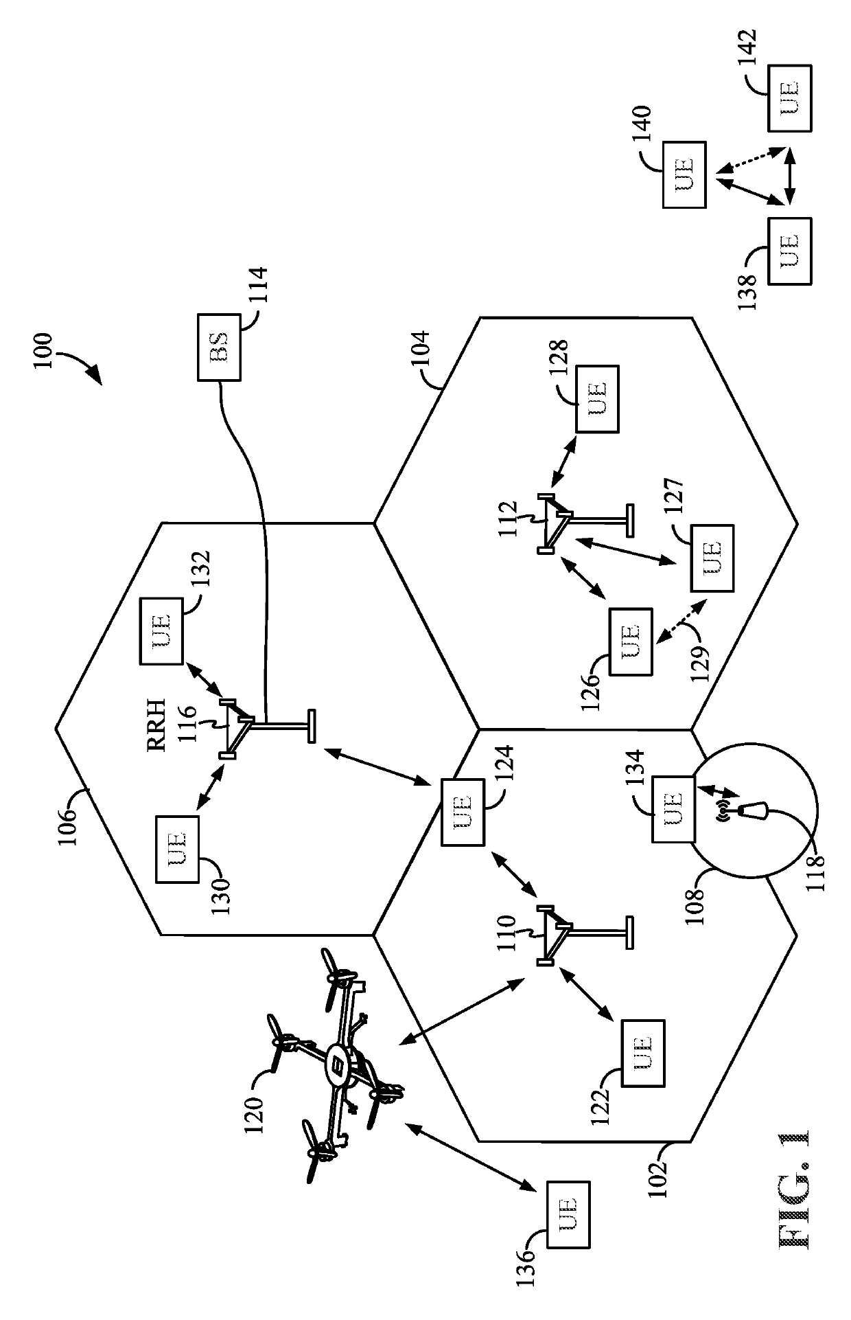
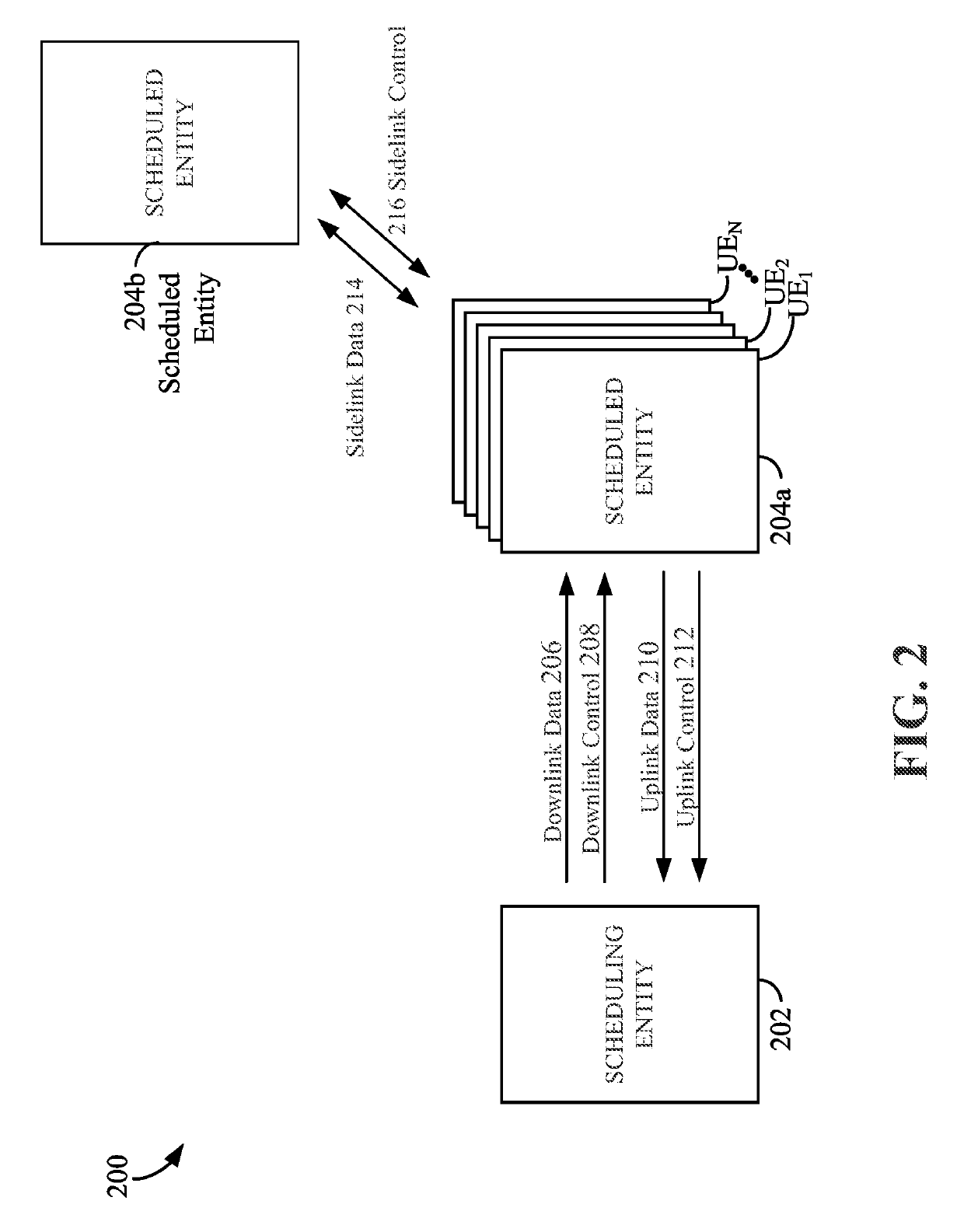
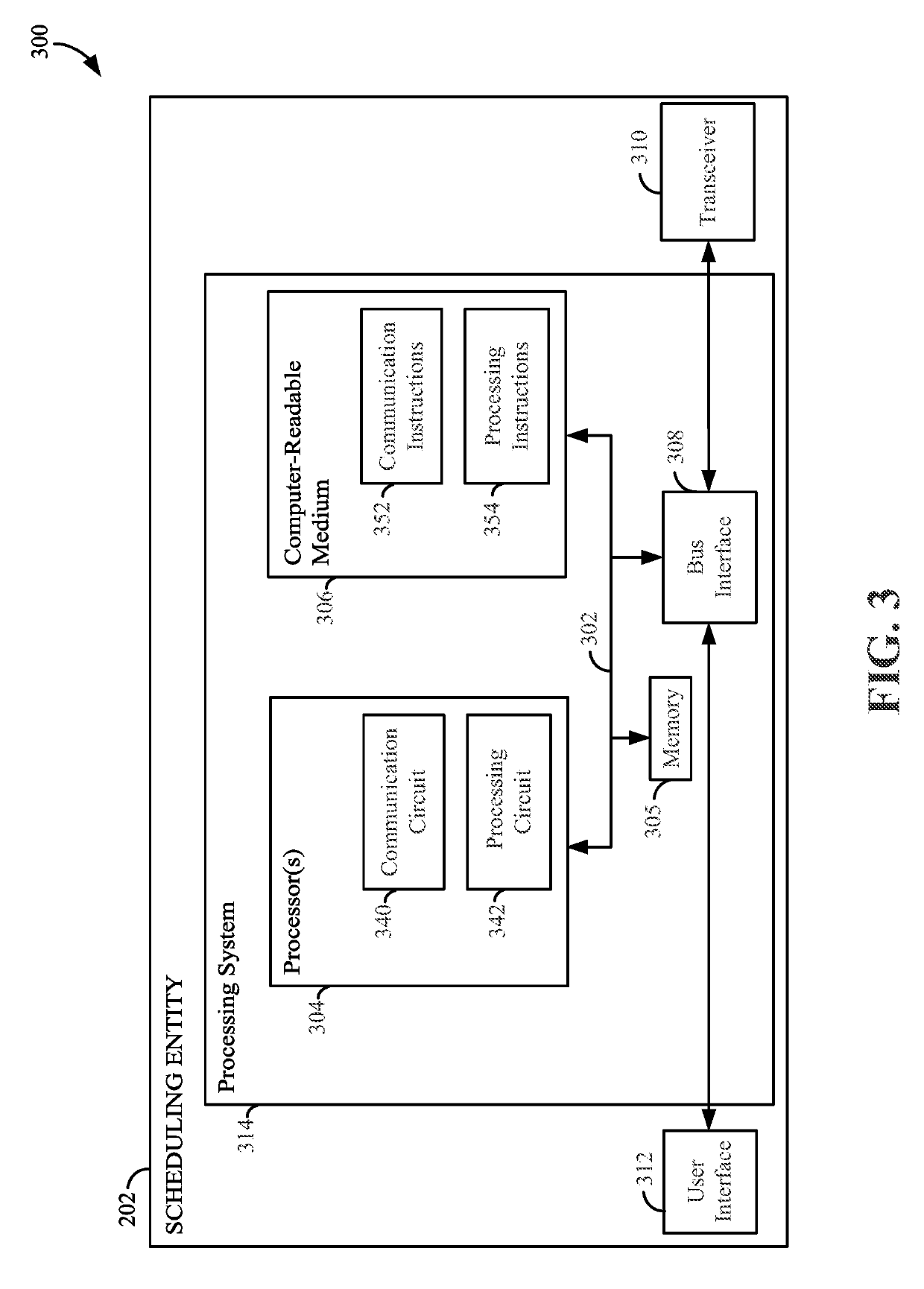
  • Clear-to-send (CTS) power control in sidelink
  • Clear-to-send (CTS) power control in sidelink
  • Clear-to-send (CTS) power control in sidelink

Examples


example a

[0143] Assume an instantaneous CQI is better than an expected CQI (e.g., obtained from a historical record) and there is not much data to transmit. In this case, using less power to transmit data in the data channel in comparison to the power used to transmit an RTS message in the RTS channel, and / or using a lower modulation and coding scheme (MCS) during transmission of data in the data channel in comparison to that used to transmit the RTS message in the RTS channel, can reduce the interference to neighboring links during the time allocated for the data channel.

example b

[0144] Assume a sidelink data transmission will be blocked by a higher priority receiver (e.g., due to TX-yielding as described above) if the data channel power is equal to the RTS channel power. In this case, the sidelink transmitter can choose to reduce its data TX power (i.e., the data channel power) to a certain extent such that it meets a TX-yielding threshold (i.e., not triggering TX-yielding). Consequently, the data transmission of the sidelink transmitter may continue without interfering with the higher priority receiver too much. That is, some interference may occur, but may be at an acceptable level.

[0145]Problems encountered due to implementations of sidelink in which the data channel power and RTS channel power are set to be the same may be overcome, for example, by use of a device with the capability of dynamically determining transmitter power and / or MCS for at least some of the channels being transmitted. In one aspect, the device may use less power in transmission of...


PUM


Abstract

A first device may configure a second device, such as a sidelink receiver, so that an interference protection zone surrounding the second device may be dynamically adjusted in size based, for example, on various objectives and / or use cases recognized by the first device. The interference protection zone may be, for example, an area surrounding the second device, within which neighboring devices may be silenced. Changes to the interference protection zone may be achieved by providing a dynamic clear-to-send (CTS) transmit power scaling parameter, that is different from a pre-assigned constant parameter for CTS power control stored at the second device, to the second device from the first device. The second device may calculate CTS channel power using at least the dynamic CTS transmit power scaling parameter and the received RTS channel power. The second device may send a CTS message in a CTS channel at the calculated CTS channel power.

Description

PRIORITY CLAIM[0001]This application claims priority to and the benefit of Provisional Patent Application No. 62 / 374,557 filed in the United States Patent Office on Aug. 12, 2016 and Provisional Patent Application No. 62 / 374,448 filed in the United States Patent Office on Aug. 12, 2016, the entire content of which is incorporated herein by reference as if fully set forth below in its entirety and for all applicable purposes.TECHNICAL FIELD[0002]The technology discussed herein relates generally to wireless communication systems, and more particularly, to dynamic power control for sidelink clear-to-send channels.INTRODUCTION[0003]Wireless communication networks are widely deployed to provide various communication services such as telephony, video, data, messaging, broadcasts, and so on. Such networks, which are usually multiple access networks, support communication for multiple users by sharing the available network resources. Within such wireless networks a variety of data services ...

Claims


Application Information

Patent Timeline
Patent Type & Authority Patents(United States)
IPC IPC(8): H04W52/02H04W52/28H04W88/08H04W88/02H04W74/00H04W52/26H04W92/18H04W74/08H04W52/24H04W52/38H04W72/08H04W52/32H04W76/14H04W72/54
CPCH04W52/0235H04W52/246H04W52/325H04W52/383H04W72/08H04W74/0816H04W76/14H04W92/18H04W52/243Y02D70/26H04W52/245H04W52/265H04W52/281H04W74/002H04W88/02H04W88/08Y02D70/00Y02D70/1242Y02D70/1262Y02D70/142Y02D70/144Y02D70/146Y02D70/164Y02D70/21Y02D70/22Y02D70/23Y02D30/70H04W72/54
Inventor LI, CHONGLI, JUNYIGUPTA, PIYUSH
Owner QUALCOMM INC
Learn More