
Double-lip seal of pneumatic spring brake chamber for vehicle

a technology of pneumatic springs and brake chambers, which is applied in the direction of brake cylinders, braking systems, braking components, etc., can solve the problems of reducing sealing function and degradation of sealing performance, and achieve constant sealing performance, prevent fluid leakage, and prevent degradation of sealing performance

Active Publication Date: 2019-05-14
MIRAEVC
View PDF9 Cites 3 Cited by
  • Summary
  • Abstract
  • Description
  • Claims
  • Application Information

AI Technical Summary

Benefits of technology

This patent is about a new way to prevent degradation in the sealing performance of a lip seal used in a pneumatic spring brake chamber. It suggests using a lip seal with a groove to catch any impurities that might damage the seal at the initial stages. This double-lip seal design ensures constant sealing performance and prevents fluid leakage, which can improve the overall performance of the brake system in vehicles.

Problems solved by technology

However, the conventional sealant has a weak contact force with the inner circumferential surface of the through-hole of the adaptor housing and the actuator rod, resulting in reduced sealing function, and impurities entering the housing may push the contacted part of the sealant, causing degradation in sealing performance.

Method used


Image

  • Double-lip seal of pneumatic spring brake chamber for vehicle
  • Double-lip seal of pneumatic spring brake chamber for vehicle
  • Double-lip seal of pneumatic spring brake chamber for vehicle

Examples


Embodiment Construction

[0019]The present invention now will be described more fully hereinafter with reference to the accompanying drawings, in which embodiments of the invention are shown. This invention may, however, be embodied in many different forms and should not be construed as limited to the embodiments set forth herein. Rather, these embodiments are provided so that this disclosure will be thorough and complete, and will fully convey the scope of the invention to those skilled in the art.

[0020]The terminology used herein is for the purpose of describing particular embodiments only and is not intended to be limiting of the invention. As used herein, the singular forms “a”, “an” and “the” are intended to include the plural forms as well, unless the context clearly indicates otherwise. It will be further understood that the terms “includes”, “comprises” and / or “comprising,” when used in this specification, specify the presence of stated features, integers, steps, operations, elements, and / or compone...


PUM


Abstract

The present disclosure relates to a double-lip seal of a pneumatic spring brake chamber for a vehicle, the double-lip seal has sealing performance between an inner circumferential surface of a through-hole of an adaptor housing and an outer circumferential surface of an actuator rod to prevent degradation in sealing performance of the lip seal, thereby maintaining constant sealing performance and preventing fluid leakage.

Description

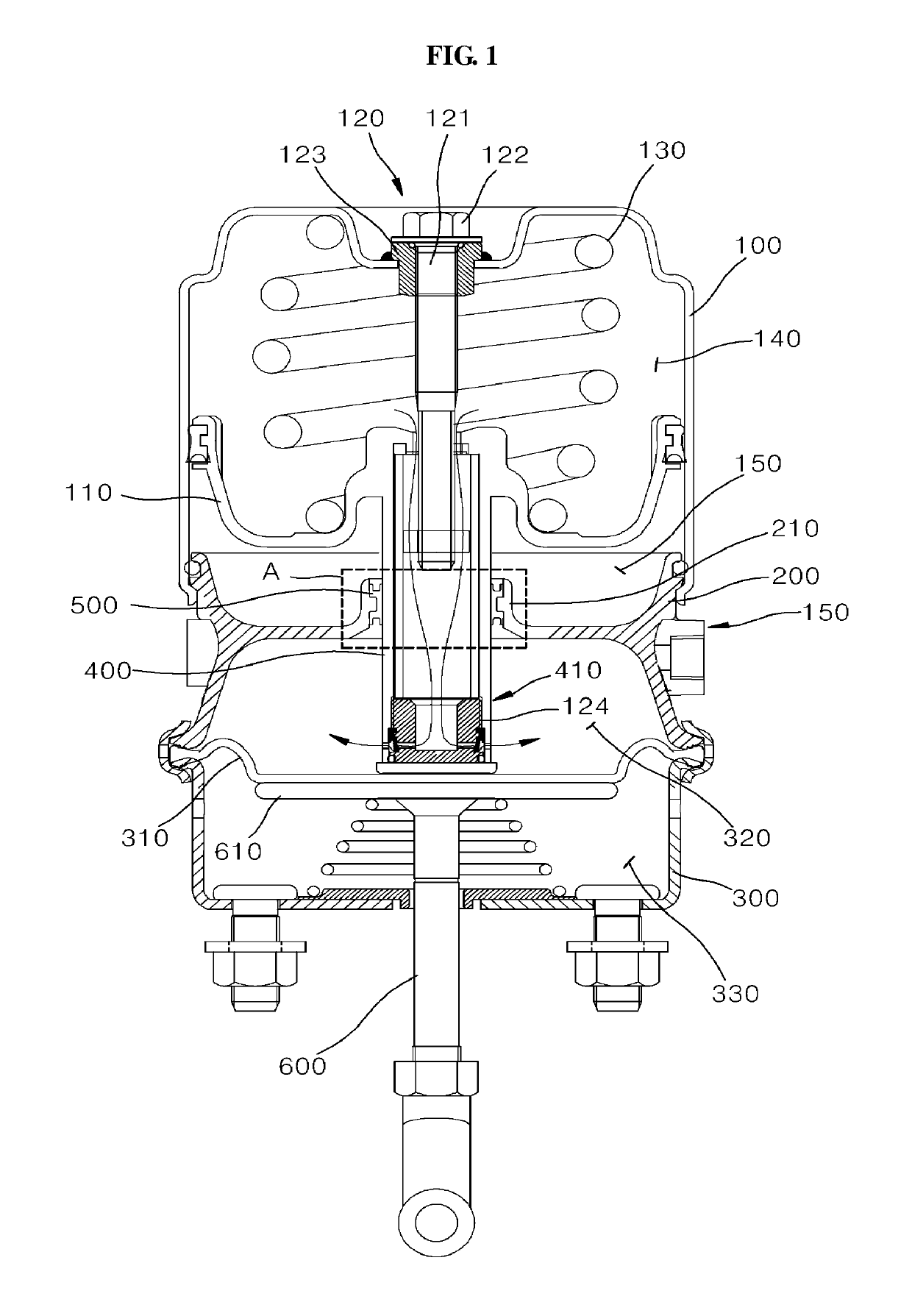
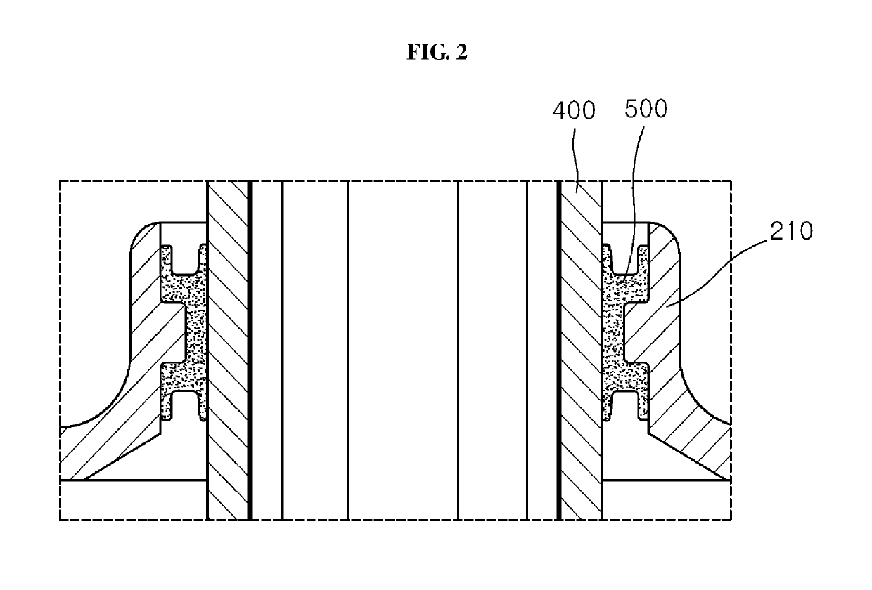
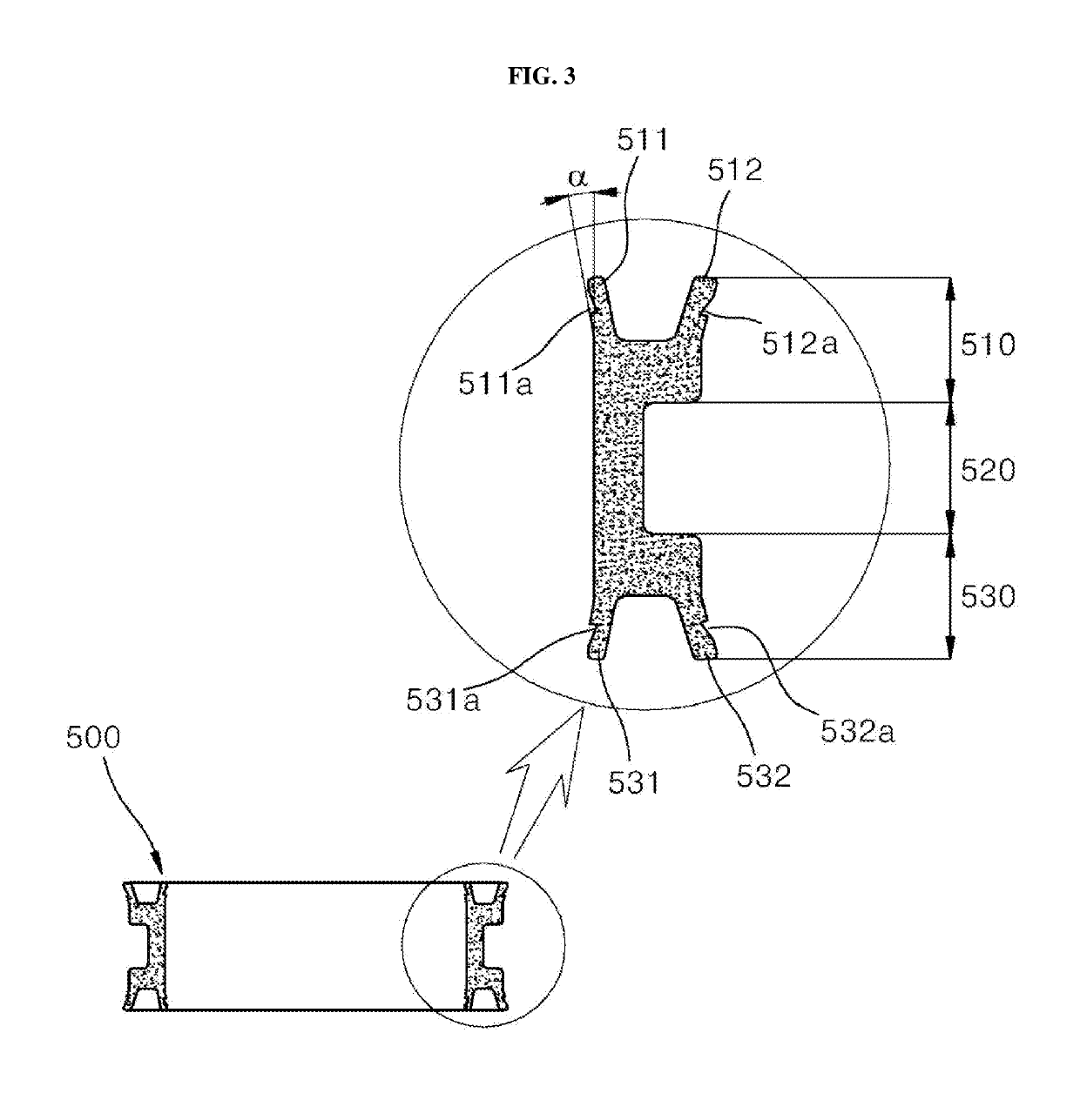
BACKGROUND OF THE INVENTION[0001]Field of the Invention[0002]The present disclosure relates to a double-lip seal of a pneumatic spring brake chamber for a vehicle, and more particularly, to a double-lip seal of a pneumatic spring brake chamber for a vehicle with increased sealing performance between an inner circumferential surface of a through-hole of an adaptor housing and an outer circumferential surface of an actuator rod to prevent fluid leakage.[0003]Description of the Related Art[0004]Large vehicles such as buses, trucks, trailers, and other heavy machinery use a brake chamber for vehicles that performs delicate and fast braking operation while high-speed driving or parking and has good braking performance.[0005]Seeing the structure of a vehicle brake chamber, the vehicle brake chamber includes a head housing, an adaptor housing and a bottom housing of a hollow shape in a sequential order from the top. On the other hand, a piston is placed between the head housing and the ada...

Claims


Application Information

Patent Timeline
Patent Type & Authority Patents(United States)
IPC IPC(8): B60T17/08F16D65/28F16D121/10F16D125/08F16D125/12F16D125/58
CPCB60T17/083F16D65/28F16D2125/585F16D2125/08F16D2125/12F16D2121/10
Inventor KIM, YEON MIN
Owner MIRAEVC
Learn More