
Hybrid energy storage module system

a technology of energy storage module and energy storage module, which is applied in the field of hybrid energy storage module system, can solve the problems of low output per unit weight, low discharge rate, and reduced output voltage, so as to prevent the decrease in the output voltage of lead storage battery modules and the deterioration of lithium battery modules, and reduce manufacturing costs. , the effect of sharp change in output power amoun

Active Publication Date: 2019-05-14
JSYOUNGTECH
View PDF17 Cites 0 Cited by
  • Summary
  • Abstract
  • Description
  • Claims
  • Application Information

AI Technical Summary

Benefits of technology

The present invention provides a hybrid energy storage module system that can handle high output requirements and is reliable. The system can allow an electric vehicle to run up to 100 km before needing to be charged. The system also improves energy efficiency and reduces sudden changes in output, resulting in a longer lifespan for the battery. Additionally, the system enhances the recovery of energy generated by regenerative braking.

Problems solved by technology

However, the lead storage battery is problematic in that the output per unit weight is low, the volume is large, the output voltage is reduced when used for a long period of time, the discharge rate is low, and the lifespan is shortened due to overheating when frequently exposed to a load requiring a high output.
In addition, the lead storage battery has a problem in that it is not suitable for charging the electric energy recovered through regenerative braking.
However, the lithium battery is very expensive.
As a result, the lifespan of the lithium battery is sharply reduced.
Furthermore, the lithium battery has a risk of fire and explosion.
For that reason, a secondary battery of low density such as a lead storage battery or the like cannot be used as a battery for an electric vehicle.
However, an electric vehicle capable of driving about 100 km when charged once has a short mileage.
However, as described above, if the lead storage battery is used for a long period of time, the output voltage thereof becomes low.
Therefore, the electric vehicle is difficult to run.
Since the lead storage battery is lower in output than the lithium battery, the lead storage battery is difficult to cope with a case where a high output is required, such as a case where an electric vehicle restarts after stoppage or a case where an electric vehicle runs on a sloping road.
The lead storage battery has a problem in that the lifespan thereof is shortened when the lead storage battery is frequently exposed to a load requiring a high discharge rate.
In addition, the lead storage battery has a problem in that it cannot be used for charging electric energy generated by regenerative braking.
This poses a problem in that a vehicle occupant or a user may feel a shock generated due to the change in the amount of energy.
Moreover, there is a problem in that the energy efficiency is low.
Furthermore, in the case of using a hybrid battery system in a plug-in hybrid car, if driving and charging are simultaneously performed while driving a range extender, a problem is posed in that a motor vehicle has to be driven by a lead storage battery while charging a lithium battery.

Method used


Image

  • Hybrid energy storage module system
  • Hybrid energy storage module system
  • Hybrid energy storage module system

Examples


Embodiment Construction

[0037]A preferred embodiment of the present invention will now be described in detail with reference to the accompanying drawings.

[0038]The embodiment to be described below is presented by way of example in order to make sure that the idea of the present invention is sufficiently delivered to those skilled in the art. Accordingly, the present invention is not limited to the embodiment described below and may be embodied in other forms. In the drawings, the width, length and thickness may be exaggerated for the sake of convenience. Throughout the specification, the same components are designated by like reference numerals.

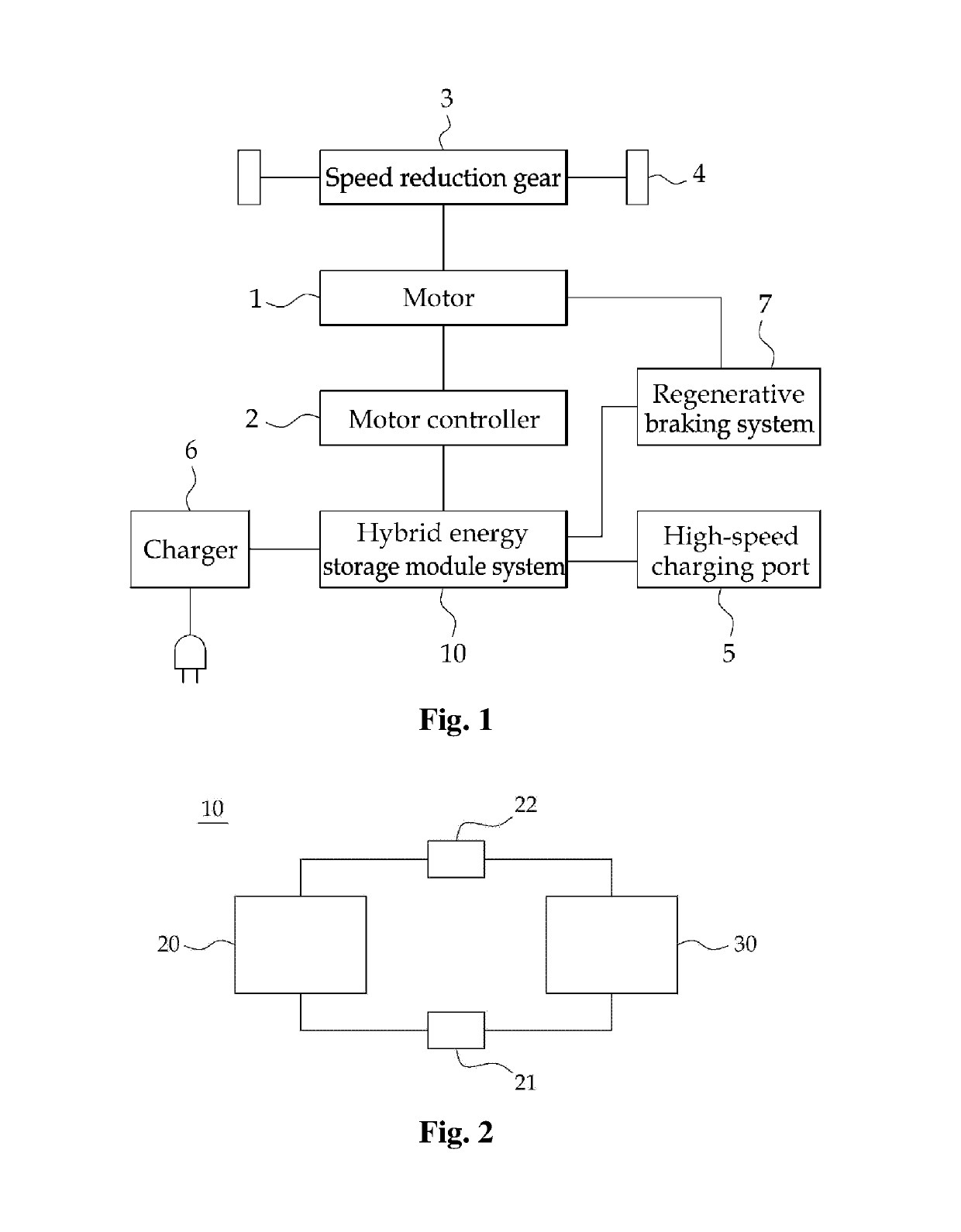
[0039]The hybrid energy storage module system according to the present invention may be used for various applications. Hereinafter, a case where the hybrid energy storage module system is used for an electric vehicle will be described by way of example. The electric vehicle includes a hybrid car (HEV), a plug-in hybrid car (PHEV), a pure electric vehicle (EV), and t...


PUM

PropertyMeasurementUnit
electric energyaaaaaaaaaa
voltageaaaaaaaaaa
voltageaaaaaaaaaa

Abstract

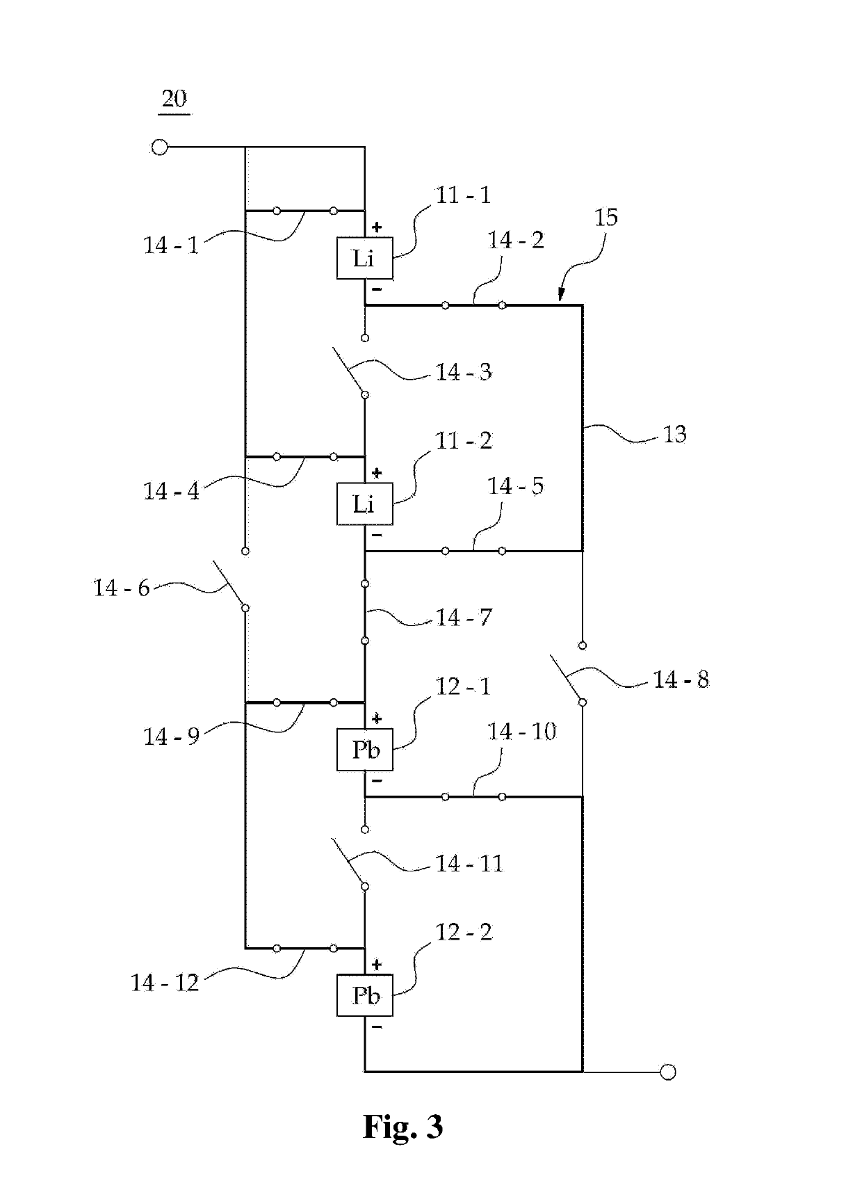
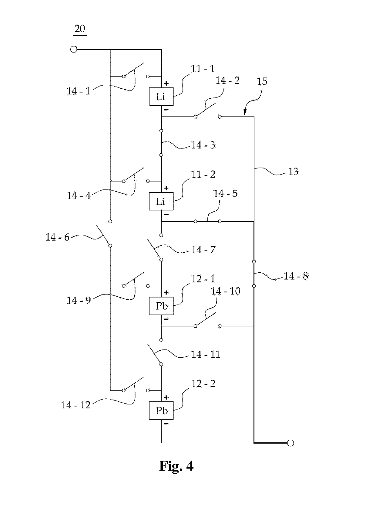
The present invention relates to an energy storage module system and, more specifically, to a hybrid energy storage module system selectively using, according to the amount of power required in a load, a lithium battery and a lead storage battery by mutually supplementing the lithium battery and the lead storage battery. According to the present invention, the hybrid energy storage module system is an energy storage module system for supplying power necessary for the driving of a load and comprises an energy storage device, a first sensing unit and a second sensing unit, and a controller. The energy storage device includes at least one lithium battery module and at least one lead storage battery module. In addition, the energy storage device includes a switching network configured so as to connect the lithium battery module and the lead storage battery module in different arrangement modes. The energy storage device is connected to both ends of a load and supplies power. The switching network can include a path for connecting the lithium battery module and the lead storage battery module, and a plurality of switches provided on the path. The first sensing unit is configured so as to measure the temperature and the voltage of the lithium battery modules, and the second sensing unit is configured so as to measure the temperature and the voltage of the lead storage battery module. The controller controls the switching network in order to change the arrangement modes of the lithium battery module and the lead storage battery module of the energy storage device.

Description

TECHNICAL FIELD[0001]The present invention relates to an energy storage module system and, more specifically, to a hybrid energy storage module system configured to selectively use a lithium battery and a lead storage battery in a complementary manner depending on a change in the amount of power required in a load.BACKGROUND ART[0002]An energy storage system is a system which separately stores residual electric power and supplies the stored electric power in a timely manner. The energy storage system may be largely divided into a physical energy storage system and a chemical energy storage system depending on the manner of storage of energy. Examples of the representative physical energy storage system include a pumping-up power generation system, a compressed air storage system, a flywheel and the like. Examples of the chemical energy storage system include a lithium battery, a lead storage battery, a NaS battery and the like.[0003]The energy storage system has been extensively stu...

Claims


Application Information

Patent Timeline
Patent Type & Authority Patents(United States)
IPC IPC(8): H02J7/00H01M10/44H01M10/48H01M10/0525B60W10/26B60L7/10H01M50/569
CPCB60L7/10B60L58/13H01M10/0525H01M10/443H01M10/486H01M10/488H02J7/00H02J7/0021B60L58/20B60L58/12B60L53/00B60L58/19B60L50/50B60W10/26B60L2240/545B60L2240/547Y02T10/7011Y02T10/7016Y02T10/7044Y02T10/7066B60L58/22B60L58/21B60L58/25B60L58/14H01M50/569B60L53/50B60L50/60Y02E60/10Y02T10/70Y02T90/12Y02T10/7072Y02T90/14B60W20/00
Inventor EUN, KEUN SOO
Owner JSYOUNGTECH
Learn More