Method and equipment for monitoring tyre wear, and vehicle on-board wear-monitoring system
- Summary
- Abstract
- Description
- Claims
- Application Information
AI Technical Summary
Benefits of technology
Problems solved by technology
Method used
Image

Examples
Embodiment Construction
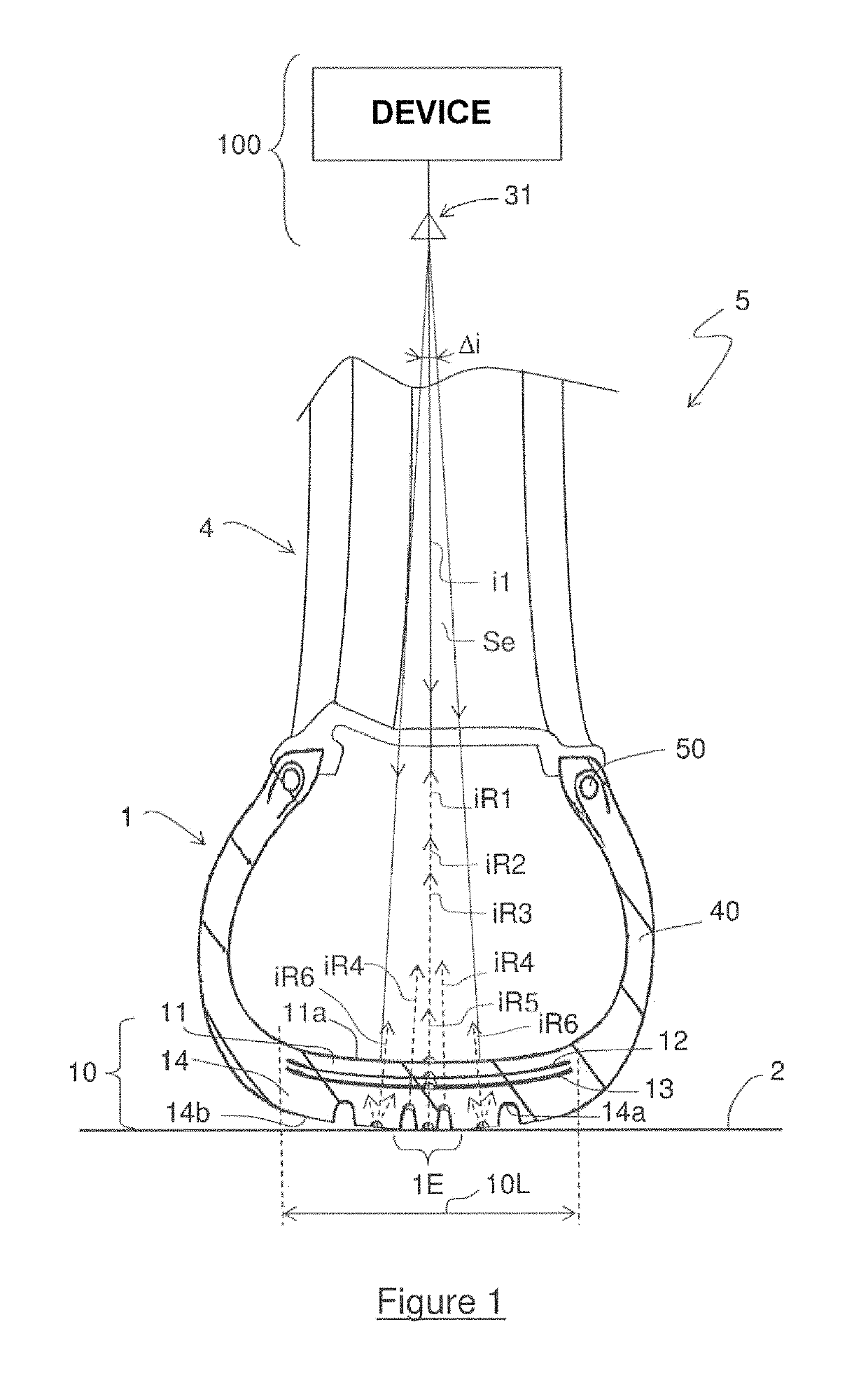
[0036]The cross-sectional view of a tire 1 on a road 2 given in FIG. 1 shows the propagation of the pulses iR1 to iR6 reflected by the tread 10 of the tire 1 and by the road 2. The pulses iR1 to iR5 are produced by successive reflections, from the interfaces formed by the tread 10, of each incident pulse i1 of a train of incident pulses with a wide frequency band, called UWB pulses, forming a transmission signal Se.
[0037]The transmitted UWB signal Se is produced by a wear monitoring device 100 equipped with an antenna 31 for transmission / reception—unidirectional for transmission and directional for reception—toward the tread 10 and within the boundaries of the width 10L of the tread. This device 100 is installed in the rim 4 of the wheel 5 of the motor vehicle (not shown) on which the tire 1 is fitted.
[0038]The tire 1 conventionally has an annular structure and the transmission / reception antenna 31, housed in the rim 4, transmits signals Se which are mainly directed radially. In the...
PUM
 Abstract
Description
Claims
Application Information
 - R&D Engineer
- R&D Manager
- IP Professional
- Industry Leading Data Capabilities
- Powerful AI technology
- Patent DNA Extraction
Browse by: Latest US Patents, China's latest patents, Technical Efficacy Thesaurus, Application Domain, Technology Topic.
© 2024 PatSnap. All rights reserved.Legal|Privacy policy|Modern Slavery Act Transparency Statement|Sitemap