
Push-button box

a push-button box and push-button technology, applied in the field of push-button boxes, can solve the problems of difficult to clearly grasp the technical features of the present designs, non-user-friendly push-button boxes, and vulnerable structures, and achieve excellent durability in operation and strength, enhance the waterproofness and the safety of the structure of the cabinet, and enhance the operability of the push-button box

Active Publication Date: 2019-05-07
KOITO ELECTRIC IND LTD
View PDF28 Cites 1 Cited by
  • Summary
  • Abstract
  • Description
  • Claims
  • Application Information

AI Technical Summary

Benefits of technology

Enhances waterproofness, safety, and user-friendliness, improves durability and strength, and facilitates easy mounting of the speaker while providing clear operation and sound guidance, making the device more accessible and effective.

Problems solved by technology

However, the pieces of prior art as disclosed in the above Patent Documents 1 and 2 are related only to the application for registration of the design, and only from the written application and the drawings attached, even a person skilled in the art, if taking the common general technical knowledge into account, may be difficult to clearly grasp the technical features of the present designs that have been provided in order to solve the above problems.
In addition, the pieces of prior art as disclosed in the Patent Documents 1 and 2 provide nothing about operation of the push button, and have presented problems that the push button is non-user-friendly especially when a visually handicapped person or the like tries to operate it by grope, and has a vulnerable structure, thereby being easy to be broken, as with the push button 4 in the conventional general push-button box 1.
Further, there has been another problem that the speaker accommodated inside the cabinet is generally disposed on the control board, and thus it is difficult not only to secure the necessary space on the control board, which is limited in area, but also to obtain a prescribed sound pressure.

Method used


Image

  • Push-button box
  • Push-button box
  • Push-button box

Examples


Embodiment Construction

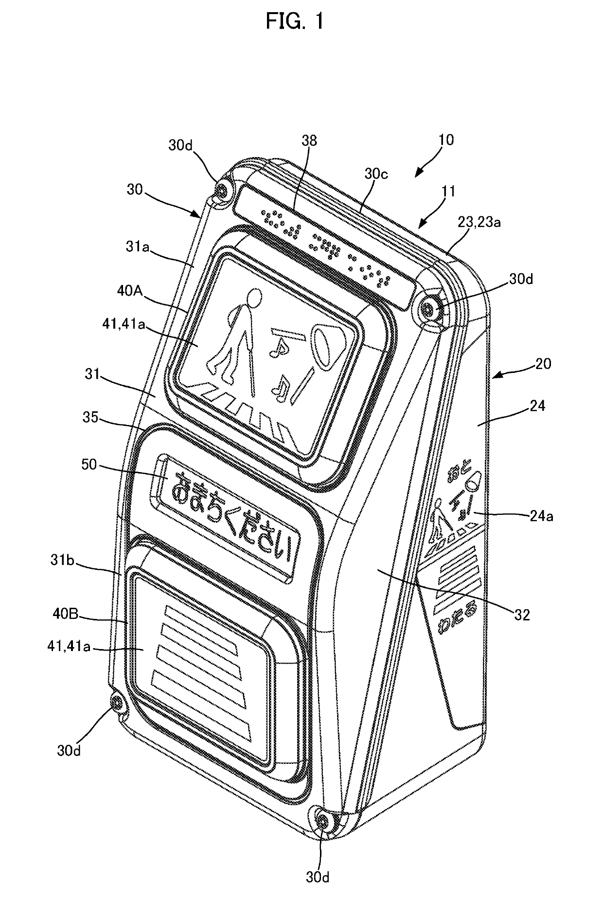
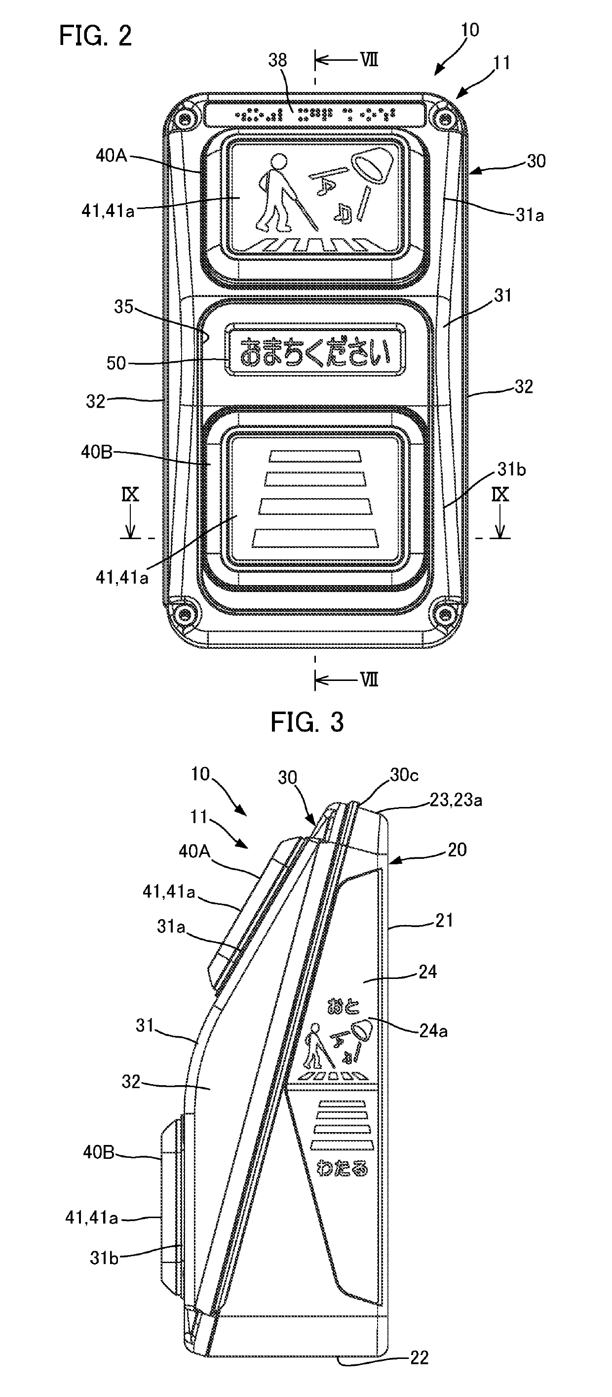
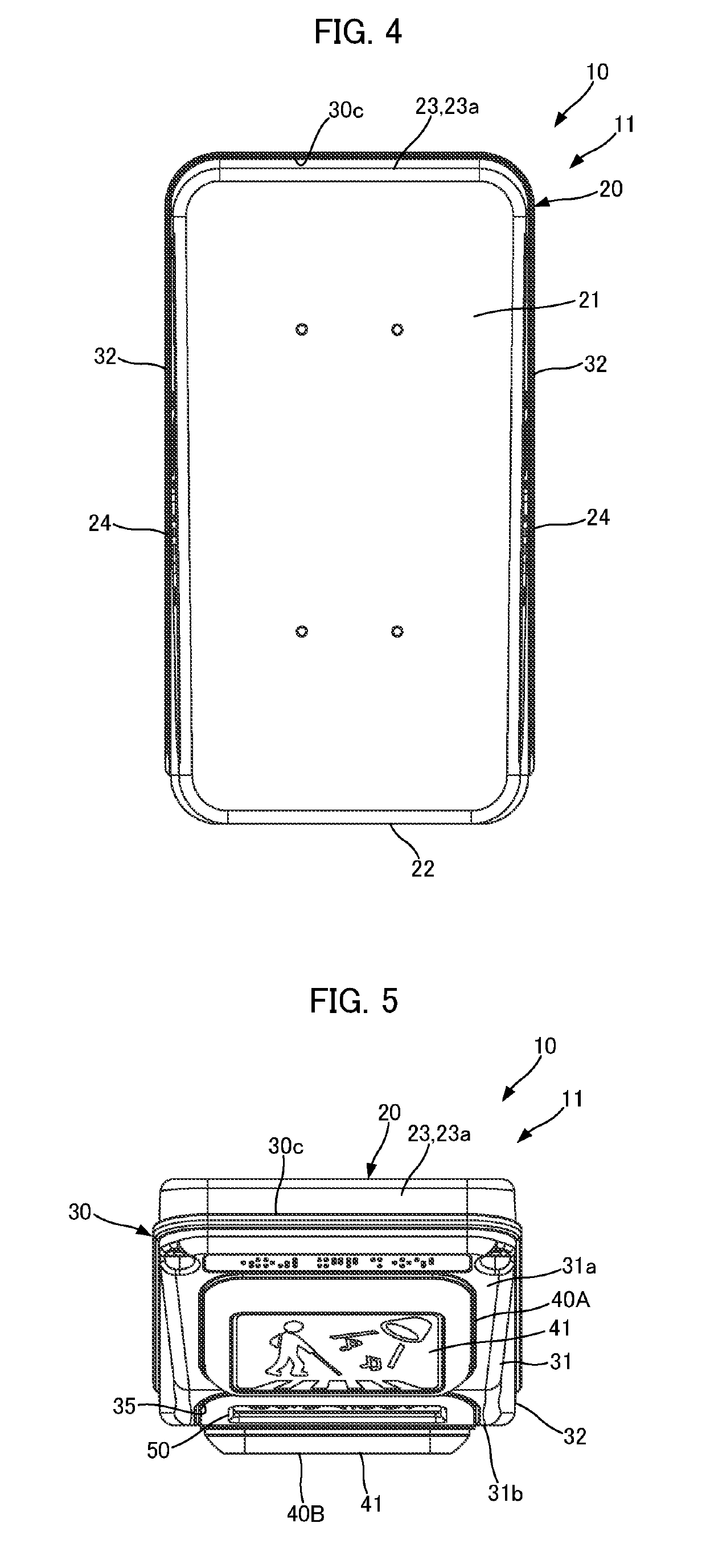
[0058]Hereinbelow, an embodiment representing the present invention will be explained with reference to the drawings.

[0059]FIG. 1 to FIG. 19 show one embodiment of the present invention.

[0060]A push-button box 10 according to the present embodiment instructs an operation of a pedestrian signal lamp device. Herein the pedestrian signal lamp device is installed at both ends of a crosswalk or the like such that it serves as an ancillary facility for the respective signal light devices for vehicle (which are not shown) that are installed at an intersection or the like of a general road.

[0061]The push-button box 10 is used, being fixed to a support such as a telegraph pole, for each pedestrian signal lamp device. The specific operations, such as the lighting color change in the signal light device for vehicle and the pedestrian signal lamp device, and the selection of the timing thereof, are controlled according to a prescribed program that is stored in the traffic signal controller (not...


PUM


Abstract

A push-button box that can enhance the waterproofness and the safety of the structure of the cabinet, and prevent a foreign matter from being left thereon, that enhances the operability of the push button, thereby being user friendly, and that is excellent in durability in operation and strength. In the push-button box 10 for instructing an operation of a pedestrian signal lamp device, a cabinet 11 that accommodates various components is formed of a base main body 20, which constitutes the rear face of the cabinet 11, being opened on the front face side, and a front case 30, which is combined with the base main body 20 so as to cover the opening thereof from forward, being provided with a push button 40, and in the state in which said front case 30 covers the opening of said base main body 20 from forward, the rear face thereof is opened downward in a diagonally rearward direction in the cabinet 11.

Description

BACKGROUND OF THE INVENTIONField of the Invention[0001]The present invention relates to a push-button box that is provided as a piece of ancillary equipment for a pedestrian signal lamp device installed at an intersection or the like of a general road, and is used for instructing an operation (for example, lighting color change) of the pedestrian signal lamp device.Description of the Related Art[0002]Conventionally, for a pedestrian signal lamp device installed at an intersection of a general road or the like, a push-button box for instructing a change of the lighting color is often installed for convenience of the pedestrian. The push-button box is fixed to an appropriate support, such as a telegraph pole or the like, close to the intersection, and on the cabinet front face of the push-button box, there is disposed a push button for instructing a change to green when the lighting color of the pedestrian signal lamp device is red.[0003]As shown in FIG. 20, a conventional push-button...

Claims


Application Information

Patent Timeline
Patent Type & Authority Patents(United States)
IPC IPC(8): G08G1/07H05K5/02G08G1/005H01H13/52H03K17/975
CPCG08G1/005G08G1/07H05K5/0239H03K17/975H01H13/52H01H13/06G08G1/095H01H13/04H05K5/03
Inventor TAKAGI, RIKA
Owner KOITO ELECTRIC IND LTD
Learn More