Receiving coupler for contactless data link
a data link and capacitance coupler technology, applied in applications, tomography, high-frequency circuit adaptations, etc., can solve the problems of critical and complex use of flexible printed circuit boards, adverse effects on signal reception, and poor coupling efficiency, so as to improve coupling capacitance, improve coupling efficiency, and increase signal level
- Summary
- Abstract
- Description
- Claims
- Application Information
AI Technical Summary
Benefits of technology
Problems solved by technology
Method used
Image
Examples
Embodiment Construction
[0035]In the following embodiments, reference is made to an upper layer, lower layer, upper conductors and lower conductors. These relate to an orientation as shown in the Figures, specifically in FIG. 2. It is obvious that such a receiving coupler may be oriented in any orientation in three-dimensional space. The terms “upper” and “lower” are only used for simplification of explanation.
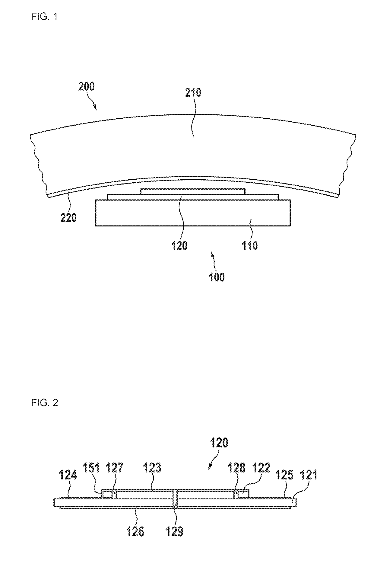
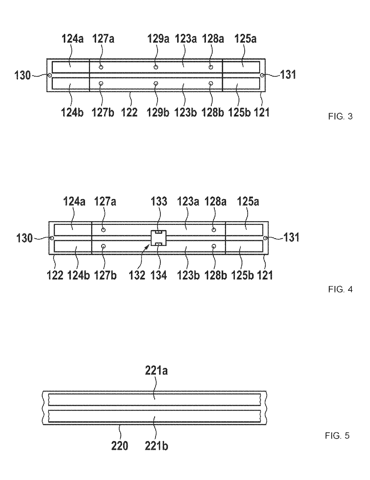
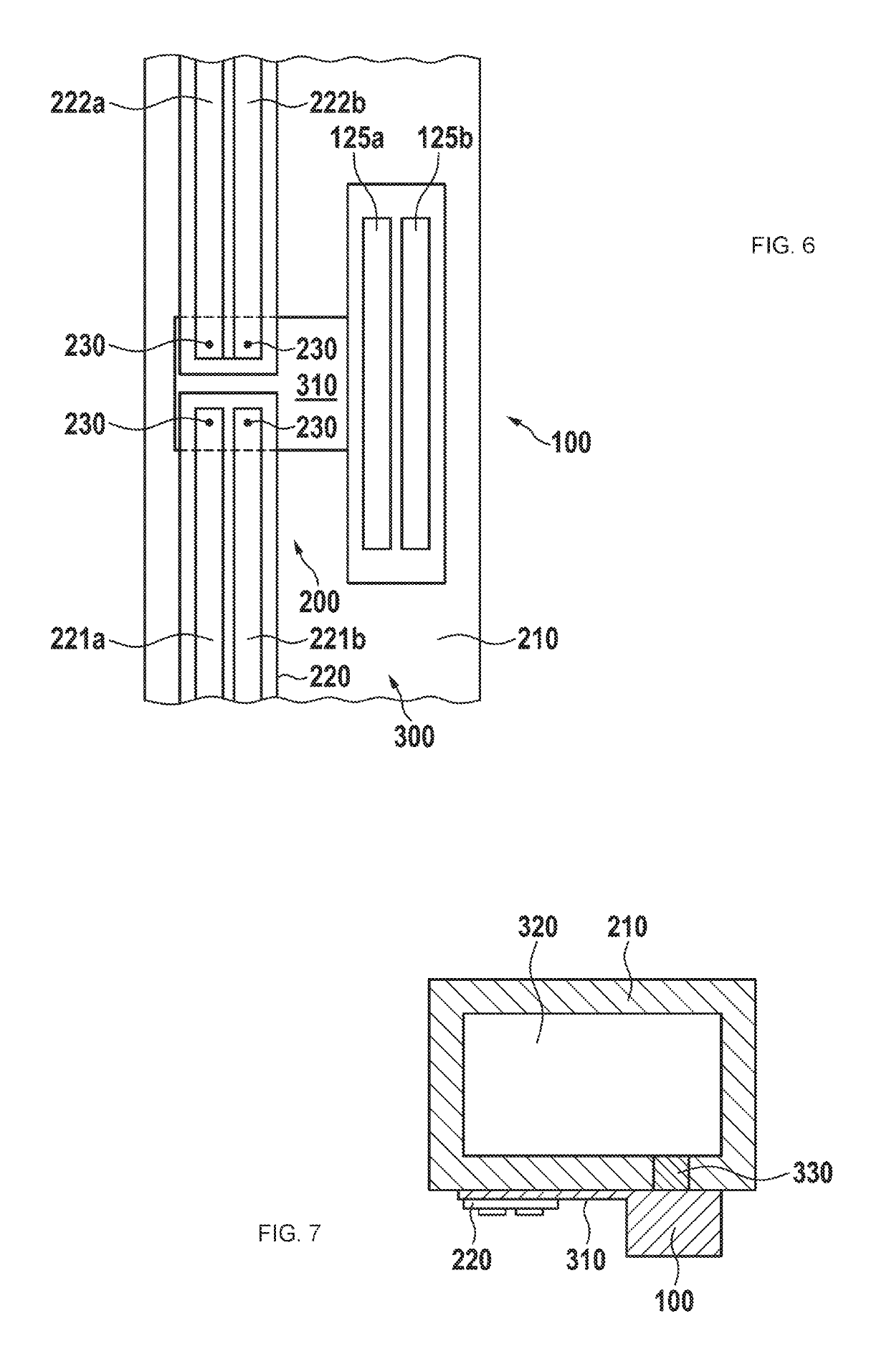
[0036]In FIG. 1, a first embodiment is shown. A contactless rotary joint which for example may be used in a computed tomography (CT) scanner may comprise a transmitting component 200 and a receiving component 100. The transmitting component 200 preferably is connected to the rotating part of a CT scanner gantry, whereas the receiving component 100 is connected to the stationary part for coupling data from the rotating to the stationary part of the CT scanner. The transmitting component 200 preferably comprises a transmitter support 210. This transmitter support may be a circular plastic carrier. It m...
PUM
 Abstract
Description
Claims
Application Information
 - R&D
- Intellectual Property
- Life Sciences
- Materials
- Tech Scout
- Unparalleled Data Quality
- Higher Quality Content
- 60% Fewer Hallucinations
Browse by: Latest US Patents, China's latest patents, Technical Efficacy Thesaurus, Application Domain, Technology Topic, Popular Technical Reports.
© 2025 PatSnap. All rights reserved.Legal|Privacy policy|Modern Slavery Act Transparency Statement|Sitemap|About US| Contact US: help@patsnap.com


