
Power generation device, power generation assembly and method of generation of power

a power generation device and power assembly technology, applied in piezoelectric/electrostriction/magnetostriction machines, dynamo-electric machines, electrical apparatus, etc., can solve the problems of consuming a lot of mechanical energy, unable to meet the needs of power generation, so as to achieve high reliability and simple structure , the effect of reducing the consumption of mechanical energy

Inactive Publication Date: 2019-04-23
HITNOLOGY CO LTD
View PDF7 Cites 2 Cited by
  • Summary
  • Abstract
  • Description
  • Claims
  • Application Information

AI Technical Summary

Benefits of technology

The present invention provides a power generation device and method that can overcome limitations in previous designs, increase efficiency and capacity, reduce mechanical energy consumption, and achieve large-scale electricity production. It uses a floor-based design that allows for direct conversion of mechanical energy into kinetic energy, resulting in higher conversion efficiency and increased practicality and reliability. The device is simple and stable, with minimal mechanical energy consumption.

Problems solved by technology

With the declining of mineral energy on earth and deteriorating of the environment, how to generate power in energy conservation and emission reduction way has become the major issue in the energy studies in the world today.
Firstly, the mechanical structure on the power-generating floor is relatively complex, and it consumes a lot of mechanical energy during the mechanical movement process, but has low generating efficiency and poor structural stability.
Secondly, the kinetic energy produced by pressure needs to be converted into mechanical energy through the movement of the gear and rack, and then the mechanical energy can be converted into electric energy to drive the generator to start, as a result, the kinetic energy collected by the power-generating floor cannot be directly and quickly converted into electric energy, and thus the utilization of kinetics is low, thereby resulting in poor electric energy production and practicality of the power-generating floor.

Method used


Image

  • Power generation device, power generation assembly and method of generation of power
  • Power generation device, power generation assembly and method of generation of power
  • Power generation device, power generation assembly and method of generation of power

Examples


Embodiment Construction

[0024]The orientation terms which are or may be mentioned in the present description, such as above, below, left, right, front, behind, front side, rear side, top, bottom, and so on, are defined relative to the construction shown in each figure, and the words “inner” and “outer” are opposite concepts, which respectively mean the direction towards or away from the geometrical center of the particular element, and thus they may be correspondingly changed according to different positions where they exist and different states of use. Therefore, these or other orientation terms should not be explained as restriction terms.

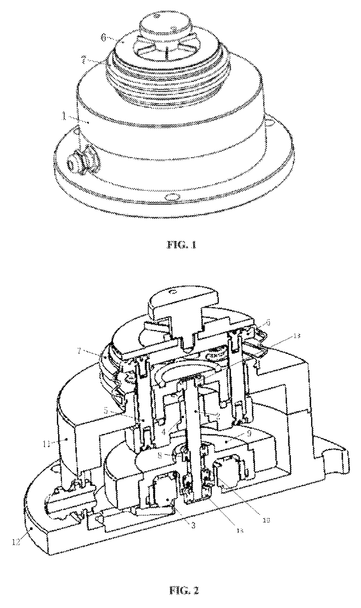
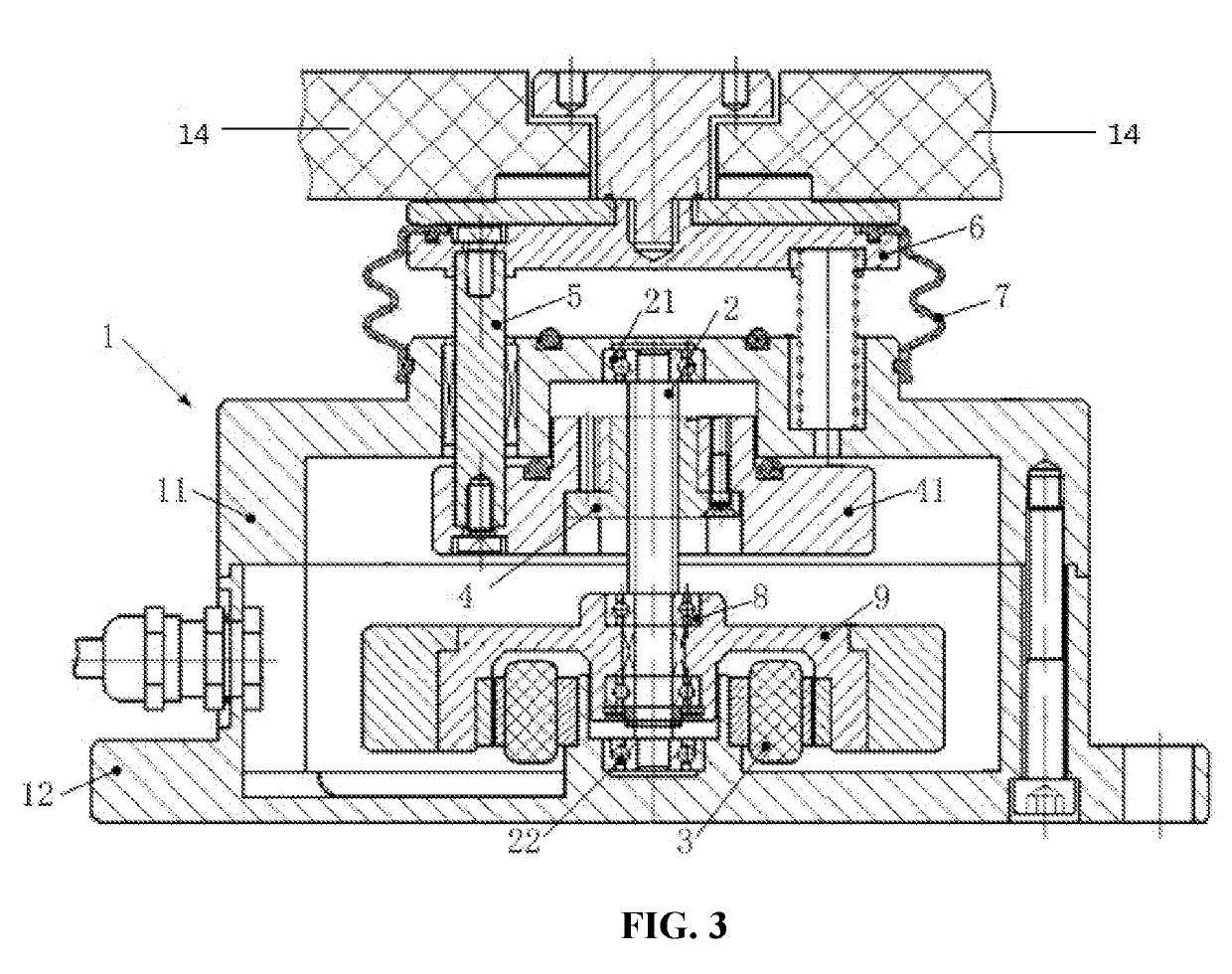
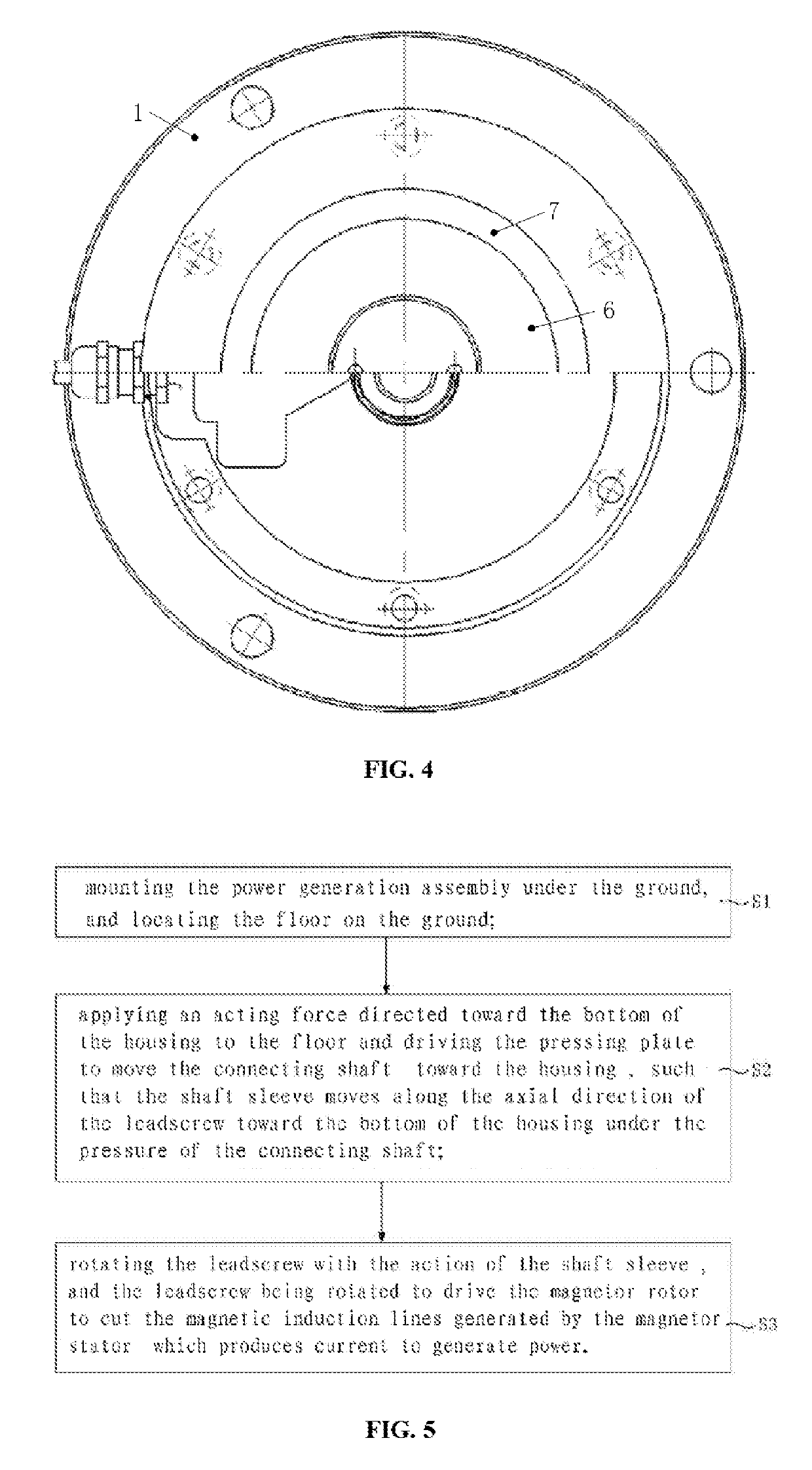
[0025]FIG. 1 is the schematic diagram of the structure of the power generation device provided by the preferred embodiment of the present invention. FIG. 2 is the section view of the power generation device provided by the preferred embodiment of the present invention. FIG. 3 is the cross-section view of the power generation device provided by the preferred embodiment o...


PUM


Abstract

The present invention discloses a power generation device, a power generation assembly and a method of generation of power. The power generation device includes a housing; a leadscrew, a first end of the leadscrew is connected to the top of the housing, and a second end of the leadscrew extends toward the bottom of the housing; a magnetic stator and a magnetic rotor, the magnetic stator is arranged at the bottom of the housing, and the magnetic rotor is mounted at the second end of the leadscrew; a shaft sleeve, a threaded hole is provided on the shaft sleeve, and the leadscrew is in screw joint within the threaded hole; a connecting shaft and a pressing plate.

Description

CROSS-REFERENCE TO RELATED APPLICATIONS[0001]The present application claims priority to Chinese Patent Application No. 201810414490.8, filed on May 3, 2018, and the entire contents thereof are incorporated herein by reference.TECHNICAL FIELD[0002]The present invention relates to the field of power generation technique, especially a power generation device, a power generation assembly and a method of generation of power.BACKGROUND ART[0003]Electric energy is the energy which is massively used in the life and production. At present, a large portion of electric energy is still generated through fire coal. With the declining of mineral energy on earth and deteriorating of the environment, how to generate power in energy conservation and emission reduction way has become the major issue in the energy studies in the world today.[0004]In the prior art, the study on power generation using road has aroused more and more attention. The main way for power generation through road is to generate...

Claims


Application Information

Patent Timeline
Patent Type & Authority Patents(United States)
IPC IPC(8): H02K7/06H02K99/00H02K7/116H02K7/02H02N2/18
CPCH02K7/06H02K99/10H02K7/02H02K7/116H02N2/18H02K7/025H02K7/08H02K7/1853Y02E60/16
Inventor KONG, SUI
Owner HITNOLOGY CO LTD
Learn More