
Backlight module and liquid crystal display device

a backlight module and liquid crystal display technology, applied in fixed installation, lighting and heating apparatus, instruments, etc., can solve the problems of inability to produce an appropriate size of many optical parts, such as a light guide plate, and the cost is relatively high, so as to reduce the cost of a large-sized product, increase the light mixing path, and facilitate implementation

Inactive Publication Date: 2019-04-23
TCL CHINA STAR OPTOELECTRONICS TECH CO LTD
View PDF17 Cites 0 Cited by
  • Summary
  • Abstract
  • Description
  • Claims
  • Application Information

AI Technical Summary

Benefits of technology

The solution reduces the light mixing height and costs associated with large-sized liquid crystal displays by using a spliced light guide plate structure, enabling thinner and more cost-effective products while maintaining high light mixing efficiency.

Problems solved by technology

An edge lighting backlight has advantages such as low power consumption and thin thickness, etc., but weight is heavy and cost is relatively high due to use of a light guide plate.
Since the size is relatively large, many optical parts, such as a light guide plate, either cannot be produced with an appropriate size, or can be produced with an appropriate size by paying huge price.
Hence, a direct lighting type backlight is generally adopted in a liquid crystal display with a supersize, although the direct lighting type backlight uses less number of light sources, has no light guide plate and has low cost, it is disadvantageous to thinning a product due to a light box being positioned high and thick appearance.

Method used


Image

  • Backlight module and liquid crystal display device
  • Backlight module and liquid crystal display device
  • Backlight module and liquid crystal display device

Examples


Embodiment Construction

[0023]Below the technical solutions in exemplary embodiments of the present disclosure are described in detail in conjunction with the accompanying drawings and detailed embodiments, and it is apparent that the described embodiments are only a part of exemplary embodiments of the present disclosure rather than all of the exemplary embodiments. Based on the embodiments of the present disclosure, all of the other embodiments obtained by those ordinarily skilled in the art without exerting creative labor fall within the protection scope of the present disclosure.

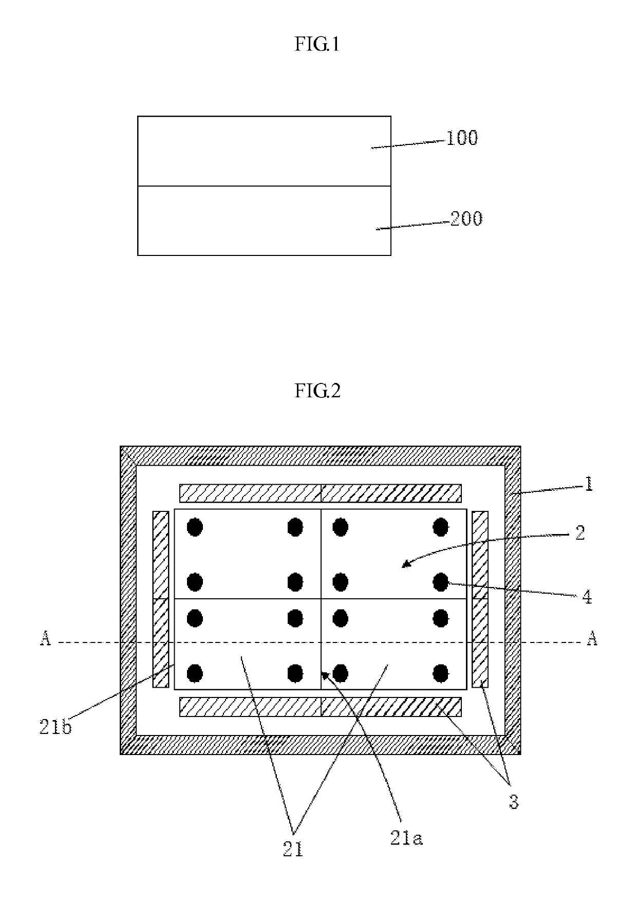
[0024]The present embodiment first provides a liquid crystal display device, referring to FIG. 1, the liquid crystal display device includes a liquid crystal panel 100 and a backlight module 200 which are oppositely disposed, the backlight module 200 provides a display light source to the liquid crystal panel 100 so that the liquid crystal panel 100 displays an image.

[0025]Further, the present embodiment further provides a back...


PUM


Abstract

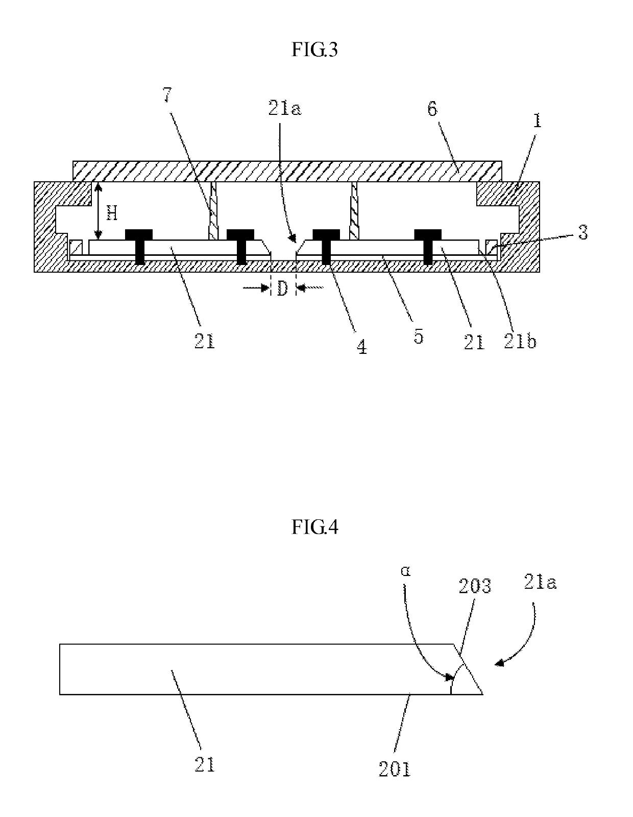
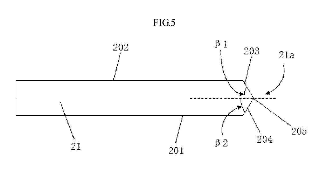
A backlight module including a back plate and a light guide plate structure and a light source assembly disposed on the back plate, wherein the light guide plate structure is mainly formed by splicing a plurality of light guide plate blocks, each of the plurality of light guide plate blocks includes a splicing end surface and at least one incident light end surface, and the light source assembly is disposed on at least one incident light end surface of the light guide plate blocks. Additionally, a liquid crystal display including the above backlight module is disclosed. The light guide plate structure in the backlight module may reduce a light mixing height of the backlight module and is advantageous to thinning the product; in addition, the structure of the light guide plate is simple and easy to be implemented, which is advantageous to lower the cost of the product.

Description

CROSS-REFERENCE TO RELATED APPLICATION[0001]This application is the U.S. national phase of PCT Application No. PCT / CN2015 / 081387 filed on Jun. 12, 2015, which claims priority to CN Patent Application No. 201510312647.2 filed on Jun. 09, 2015, the disclosures of which are incorporated in their entirety by reference herein.TECHNICAL FIELD[0002]The present disclosure relates to liquid crystal display technical field, and more particularly to a backlight module and a liquid crystal display device.BACKGROUND ART[0003]With the evolution of photoelectricity and semiconductor technologies, the vigorous development of a Flat Panel Display has been driven, while a Liquid Crystal Display (LCD) has become the market mainstream due to lots of advantageous properties, such as high utilization efficiency of space, low power consumption, no radiation and low electromagnetic interference, etc., among many flat panel displays. A LCD generally includes a Liquid Crystal Panel and a Back Light Module (B...

Claims


Application Information

Patent Timeline
Patent Type & Authority Patents(United States)
IPC IPC(8): F21V8/00
CPCG02B6/0078G02B6/0051G02B6/0068G02B6/0088F21S8/00F21V5/08F21V17/12G02F1/133606G02F1/133607
Inventor FAN, YONGQIN, ZUOYUAN
Owner TCL CHINA STAR OPTOELECTRONICS TECH CO LTD
Learn More