Technique for preventing air lock through stuttered starting and air release slit for pumps

a technology of air lock and air release, which is applied in the direction of machine/engine, engine starter, positive displacement liquid engine, etc., can solve the problems of impellers not being able to create enough pressure to overcome back pressure, pumps tend to fail to pump water, etc., and achieve better and more cost-effective effects

Active Publication Date: 2019-04-23
FLOW CONTROL LLC
View PDF63 Cites 2 Cited by
  • Summary
  • Abstract
  • Description
  • Claims
  • Application Information

AI Technical Summary

Benefits of technology

[0025]One advantage of the present invention is that it provides a new, better and more cost effective way to prevent air lock, e.g., in centrifugal pumps.

Problems solved by technology

When this occurs the pump tends to fail to pump water and the air must be expelled or pushed out of the system before the pump can operate as intended.
With air inside the impeller housing, the impellers cannot create enough pressure to overcome the back pressure from the outlet hose.
However, the system in U.S. Pat. No. 5,545,012 does not always clear the air lock and is more complex than the system proposed in this document.
However, the techniques in U.S. Pat. Nos. 4,087,994 and 4,913,620 are both unnecessarily complex and because of this are cost prohibitive in many situations.

Method used


Image

  • Technique for preventing air lock through stuttered starting and air release slit for pumps
  • Technique for preventing air lock through stuttered starting and air release slit for pumps
  • Technique for preventing air lock through stuttered starting and air release slit for pumps

Examples


Embodiment Construction

Details of the Present Invention

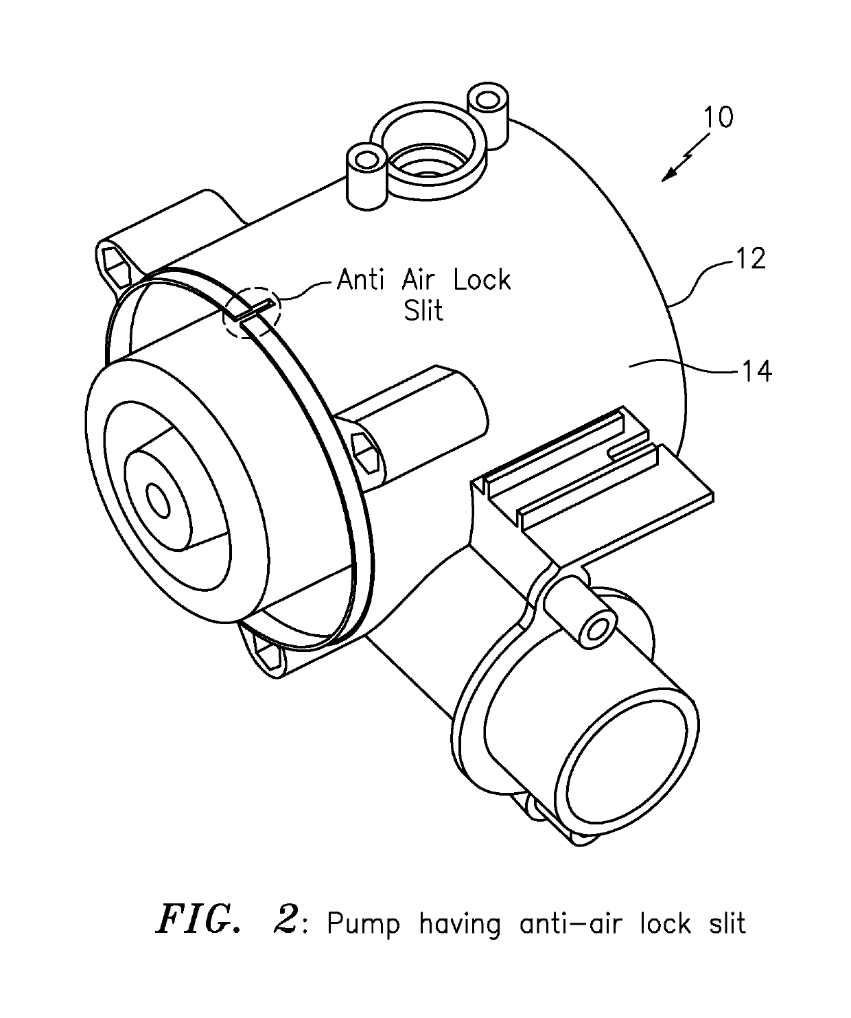
[0036]FIGS. 2-7 shows the present invention in the form of apparatus generally indicated as 10, including a pumping system, featuring a pump 12 and a control circuit 20 (see FIG. 7).

[0037]By way of example, FIG. 2 shows the pump 12 which may include an impeller housing 14 configured with at least one slit (aka “an anti air lock slit”) at the top for trapped air to leave the impeller housing 14 once the pump 12 has been submerged. The pump 12 may take the form of a centrifugal pump, as well as other types or kinds of pumps either now known or later developed in the future. In FIG. 2, the slit may be configured substantially at the top of the impeller housing of the pump, although the scope of the invention is intended to include configuring the slit at other locations as long as trapped air can be released from inside the impeller housing 14. Moreover, the scope of the invention is not intended to be limited to any particular type, kind or configuratio...


PUM


Abstract

Apparatus, including a pumping system, is provided featuring a pump and a control circuit. The pump has an impeller housing configured with a slit at the top for trapped air to leave the impeller housing once the pump has been submerged. The control circuit is configured to cycle the pump on and off for a predetermined number of cycles so that the trapped air will float to the top and be expelled out the slit when the pump is cycled off. The control circuit is configured to leave the pump on after the predetermined number of cycles.

Description

CROSS-REFERENCE TO RELATED APPLICATION[0001]This application claims benefit to provisional patent application Ser. No. 61 / 659,631, filed 14 Jun. 2012, which is hereby incorporated by reference in its entirety.BACKGROUND OF THE INVENTION[0002]1. Field of the Invention[0003]This invention relates to a pump; and more particularly, relates to a centrifugal pump.[0004]2. Description of Related Art[0005]It is known in the art that if, e.g., a centrifugal pump, is turned on prior to being submerged air can become trapped inside of the housings containing the impellers causing them to pump a gas / liquid mixture instead of the pure liquid mixture they were designed to pump. When this occurs the pump tends to fail to pump water and the air must be expelled or pushed out of the system before the pump can operate as intended. When the pump fails, this situation is known as air lock.[0006]FIG. 1 shows an air locked pump that is known in the art having a motor and an impeller for pumping an air / wa...

Claims


Application Information

Patent Timeline
Patent Type & Authority Patents(United States)
IPC IPC(8): F04D15/00F04D9/00F04D13/08
CPCF04D15/0094F04D9/003F04D9/006F04D13/086F04D15/0066F05D2260/85
Inventor LOPES, JEFFREYESTRADA, JESUSTEED, KEVIN
Owner FLOW CONTROL LLC
Why Eureka
Try Eureka