
Wedge shaped cells in a wireless communication system

a wireless communication system and cell technology, applied in the field of wireless communication, can solve the problems of high latency, bandwidth limitations or high latency problems, and the inability of aircraft platforms to become easily and cheaply connected to communication networks

Active Publication Date: 2019-04-09
SMARTSKY NETWORKS
View PDF26 Cites 7 Cited by
  • Summary
  • Abstract
  • Description
  • Claims
  • Application Information

AI Technical Summary

Benefits of technology

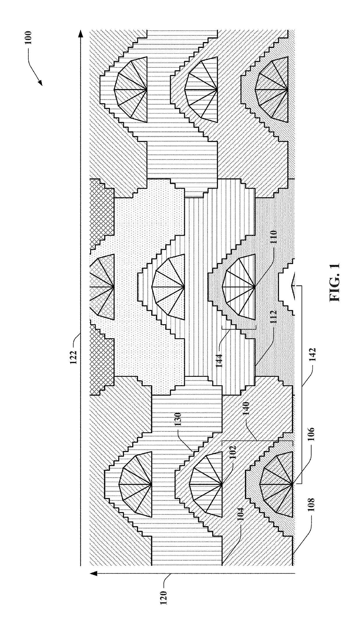
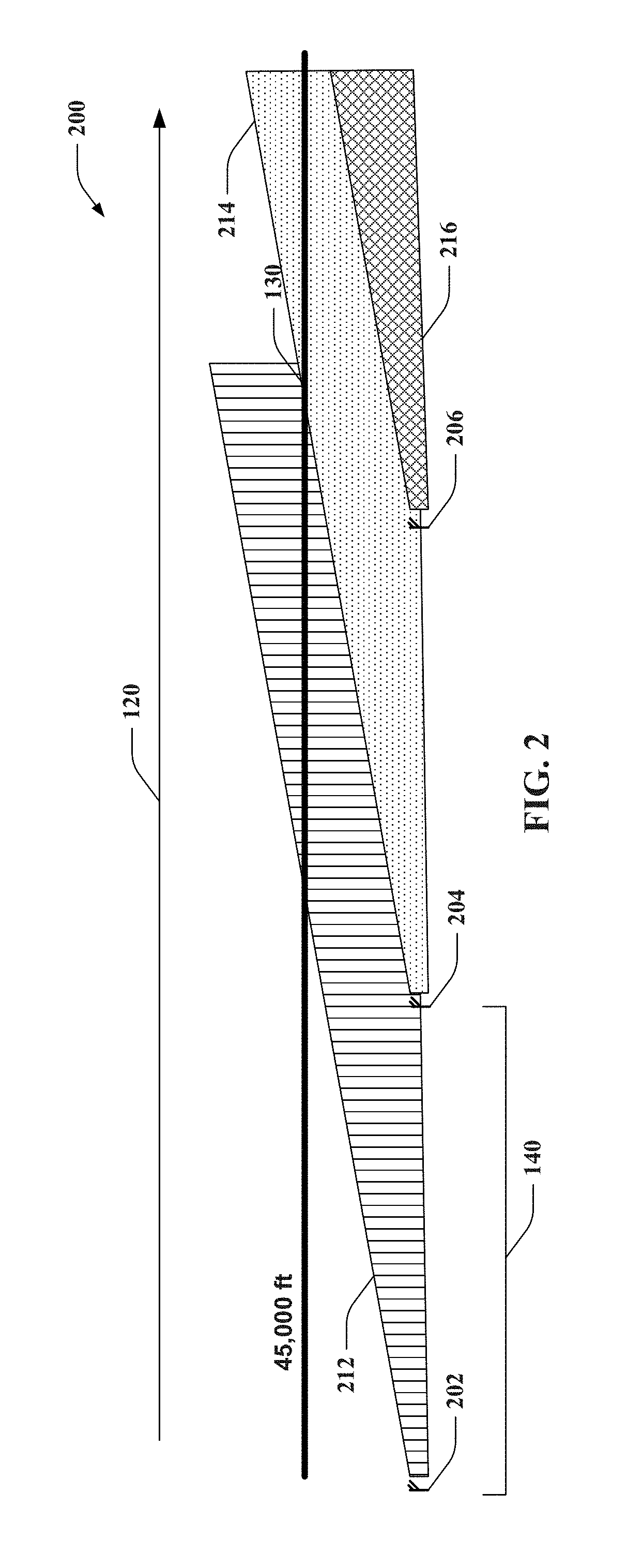
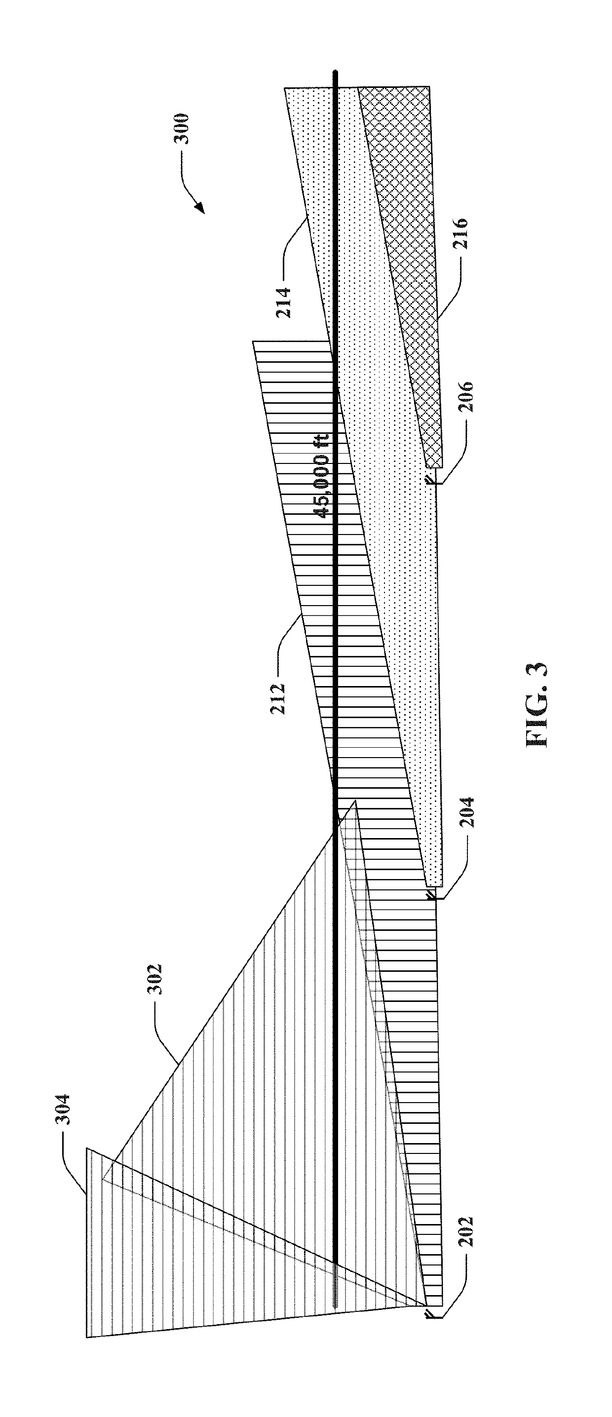
The patent is about using multiple antennas to provide wireless coverage for aircraft at various altitudes. By aligning and offsetting the base stations, the coverage area can be expanded up to a certain height and provide continuous coverage. The technical effects include improved communication coverage for high-altitude aircraft and more optimized use of multiple antennas for better coverage.

Problems solved by technology

However, in spite of the familiarity that people have with remaining continuously connected to networks while on the ground, people generally understand that easy and / or cheap connectivity will tend to stop once an aircraft is boarded.
Aviation platforms have still not become easily and cheaply connected to communication networks, at least for the passengers onboard.
Attempts to stay connected in the air are typically costly and have bandwidth limitations or high latency problems.
Moreover, passengers willing to deal with the expense and issues presented by aircraft communication capabilities are often limited to very specific communication modes that are supported by the rigid communication architecture provided on the aircraft.
With focus on the horizontal plane, however, these existing antennas may be unable to support connectivity for aircraft traveling above an elevation of the coverage area.

Method used


Image

  • Wedge shaped cells in a wireless communication system
  • Wedge shaped cells in a wireless communication system
  • Wedge shaped cells in a wireless communication system

Examples


Embodiment Construction

[0016]Some example embodiments now will be described more fully hereinafter with reference to the accompanying drawings, in which some, but not all example embodiments are shown. Indeed, the examples described and pictured herein should not be construed as being limiting as to the scope, applicability or configuration of the present disclosure. Rather, these example embodiments are provided so that this disclosure will satisfy applicable legal requirements. Like reference numerals may be used to refer to like elements throughout. Furthermore, as used herein, the term “or” is to be interpreted as a logical operator that results in true whenever one or more of its operands are true.

[0017]Some example embodiments described herein provide architectures for improved air-to-ground (ATG) wireless communication performance. In this regard, some example embodiments may provide for base stations having antenna structures that facilitate providing wireless communication coverage in vertical an...


PUM


Abstract

Aspects described herein relate to a network for providing air-to-ground wireless communication in various cells. The network includes a first base station array, each base station of which includes a respective first antenna array defining a directional radiation pattern that is oriented in a first direction, wherein each base station of the first base station array is disposed spaced apart from another base station of the first base station array along the first direction by a first distance. The network also includes a similar second base station array where the second base station array extends substantially parallel to the first base station array and is spaced apart from the first base station array by a second distance to form continuous and at least partially overlapping cell coverage areas between respective base stations of the first and second base station arrays.

Description

CROSS-REFERENCE TO RELATED APPLICATIONS[0001]This application is a continuation of U.S. application Ser. No. 15 / 345,527 filed Nov. 8, 2016, which is a continuation of U.S. application Ser. No. 15 / 017,794 filed Feb. 8, 2016, (now patented as U.S. Pat. No. 9,503,912 which issued on Nov. 22, 2016), which is a continuation of U.S. application Ser. No. 14 / 681,429 filed Apr. 8, 2015, (now patented as U.S. Pat. No. 9,294,933 which issued on Mar. 22, 2016), which is a continuation of U.S. application Ser. No. 13 / 832,385 filed Mar. 15, 2013 (now patented as U.S. Pat. No. 9,008,669 which issued on Apr. 14, 2015), the entire contents of which are hereby incorporated herein by reference.TECHNICAL FIELD[0002]Example embodiments generally relate to wireless communications and, more particularly, relate to employing wedge shaped cells to provide continuous wireless communication at various distances and altitudes.BACKGROUND[0003]High speed data communications and the devices that enable such commu...

Claims


Application Information

Patent Timeline
IPC IPC(8): H04W40/00H04W16/12H04B7/185H04W16/24H04W16/30H04W36/32H04W88/08
CPCH04W16/30H04B7/18506H04W16/24H04W36/32H04W16/12H04W88/08H04W36/328
Inventor HYSLOP, DOUGLAS
Owner SMARTSKY NETWORKS
Learn More