
Solar cell monitoring device

a monitoring device and solar cell technology, applied in the direction of measurement devices, photovoltaic monitoring, instruments, etc., can solve the problems of increased manufacturing costs, easy burnout of instruments, increased risk of fire in instruments, etc., to improve monitoring reliability, accurate and rapid recognition and inspection, and quick solve breakdowns

Inactive Publication Date: 2019-04-02
SOLARPLAY CO LTD
View PDF8 Cites 0 Cited by
  • Summary
  • Abstract
  • Description
  • Claims
  • Application Information

AI Technical Summary

Benefits of technology

The solution enhances monitoring reliability, simplifies the configuration, reduces manufacturing costs, and allows for installation in various environments by eliminating electromagnetic interference and complex wiring, while enabling efficient breakdown detection and maintenance.

Problems solved by technology

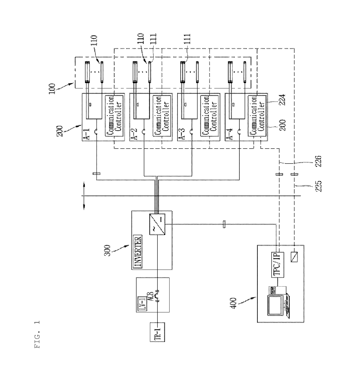
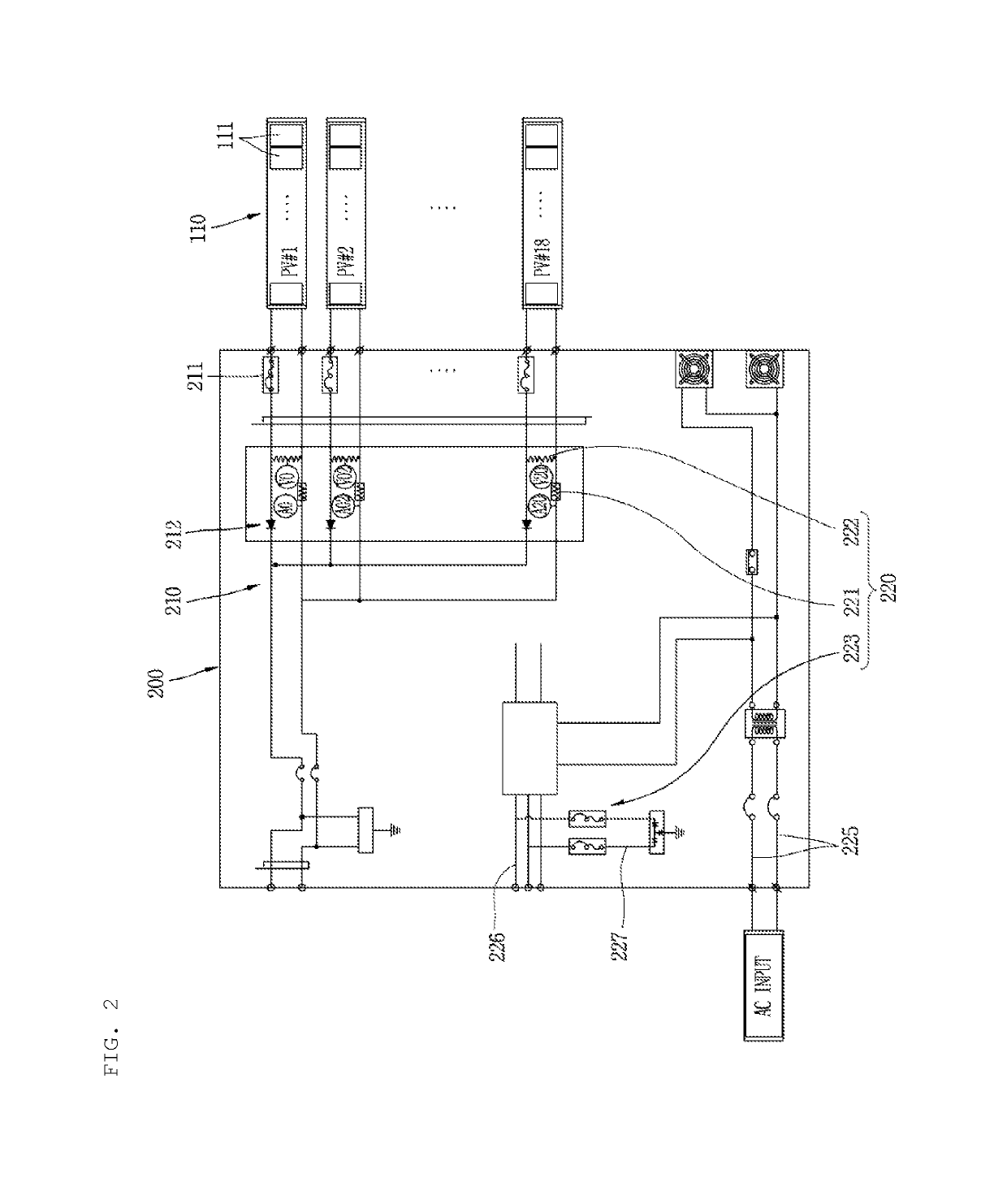
First, the instrument, which constitutes the string monitoring device, is vulnerable to various types of electromagnetic disturbances such as lightning surge, switching surge, and electromagnetic waves inputted from the outside through the electric power line 225, the communication line 226, the ground wire 227, and the like, and as a result, the instrument is easily burnt out, and there is a risk of fire in the instrument.
Second, the instrument, which constitutes the string monitoring device, not only generates heat and electromagnetic noise during the operation, but also is vulnerable to electromagnetic, thermal, and mechanical environments, such that it is necessary to provide a protective device and a heat dissipation device, and as a result, there is a drawback in that manufacturing costs are increased, and an installation place of the connection board is restricted.
Third, separate wires need to be installed in order to be supplied with alternating current power at all times for operating the string monitoring device, and as a result, there is a drawback in that a wiring structure is complicated, and alternating current power is applied to the wires at all times even in the nighttime when the photovoltaic power generation is stopped.
Fourth, each of the string circuits 210 is connected to a common terminal of plus and minus electrodes in the connection board 200, and as a result, the measurement of a voltage of the string circuit 210 is not meaningful because of an equal terminal voltage, but the measurement of a current of the string circuit 210 is effective. However, the measurement of the current often varies depending on a change in weather, and as a result, reliability deteriorates, only whether the power generation is performed may be confirmed, and there is a limitation in recognizing a cause of a breakdown.
Fifth, because the photovoltaic power generation system has a high capacity, electric power of the single string circuit 210 is very low in consideration of the entire photovoltaic power generation system, and as a result, an effect of quality of the individual string circuit 210, which affects an overall power generation amount, is insignificant. Therefore, the string monitoring is often omitted, such that the number of string circuits connected to the single inverter 300 is 100 to 300 because of a high capacity of the inverter 300, and as a result, there is a limitation in determining quality of a power generation state only by using input and output values of the inverter 300.

Method used


Image

  • Solar cell monitoring device
  • Solar cell monitoring device
  • Solar cell monitoring device

Examples


Embodiment Construction

[0040]Hereinafter, an exemplary embodiment of a solar cell monitoring device according to the present invention will be described with reference to the accompanying drawings.

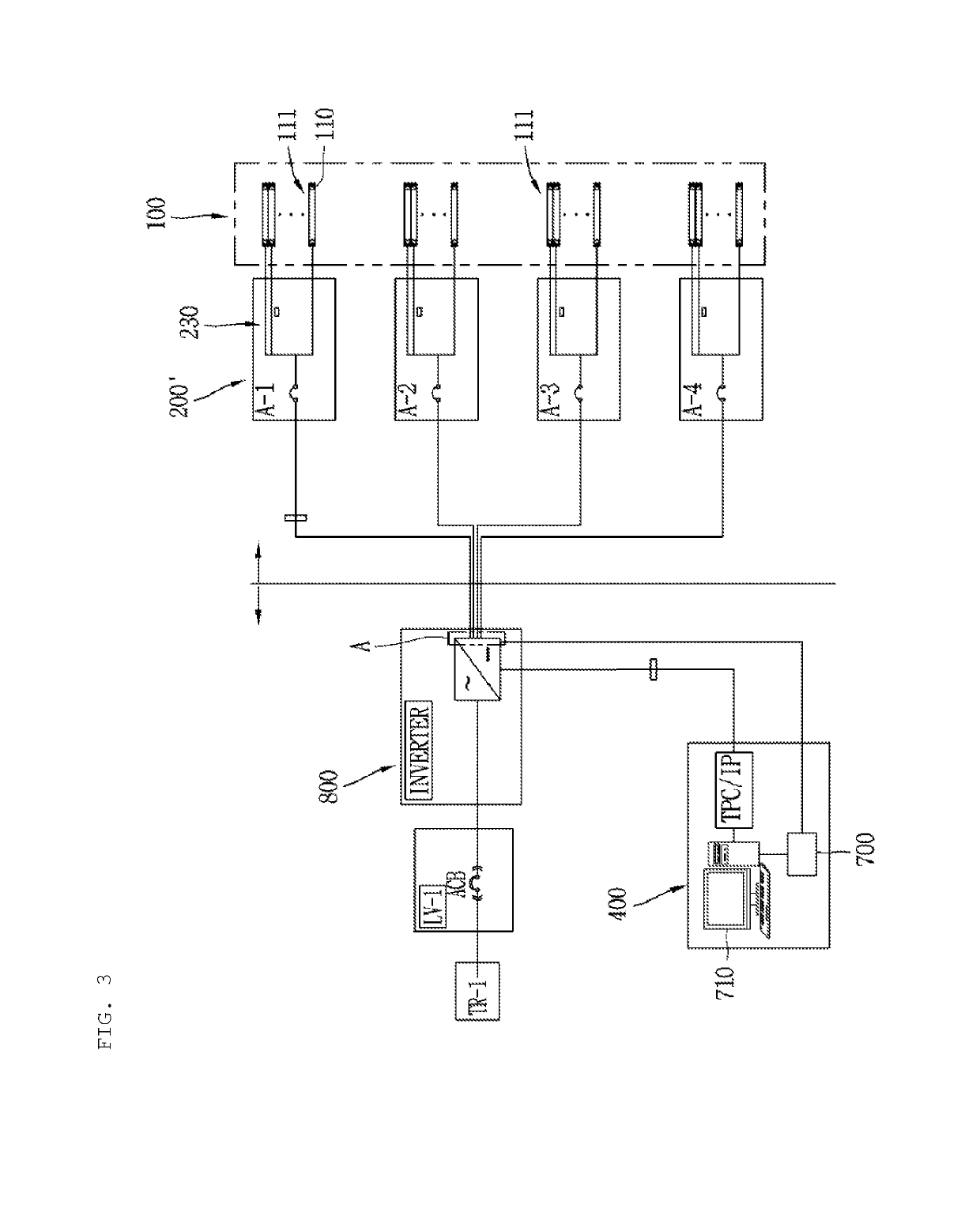
[0041]FIG. 3 is a system diagram of a photovoltaic power generation system provided with a solar cell monitoring device according to an exemplary embodiment of the present invention. FIG. 4 is a circuit diagram illustrating the solar cell monitoring device provided with a connection board and a solar cell array unit according to the exemplary embodiment of the present invention. FIG. 5 is a circuit diagram illustrating the solar cell monitoring device according to the exemplary embodiment of the present invention.

[0042]First, as illustrated in FIG. 3, a photovoltaic power generation system provided with a solar cell monitoring device according to an exemplary embodiment of the present invention includes a solar cell array unit 100, connection boards 200′, a terminal block 500, detection elements 600, a measureme...


PUM


Abstract

A solar cell monitoring device includes: an inverter; connection boards which include multiple string circuits, respectively; a terminal block which is provided at an input side of the inverter, and includes multiple branch terminals which are connected to wires that are connected to the connection boards, respectively and supply direct current power to the inverter; detection elements which are provided at a side of the branch terminals; and a measurement unit which measures the currents of the wires which are detected by the detection elements.

Description

CROSS REFERENCE TO PRIOR APPLICATIONS[0001]This application is a National Stage Application of PCT International Patent Application No. PCT / KR2016 / 006920 filed on Jun. 29, 2016, under 35 U.S.C. § 371, which claims priority to Korean Patent Application No. 2015-0092625 filed on Jun. 30, 2015, which are all hereby incorporated by reference in their entirety.BACKGROUND OF THE INVENTIONField of the Invention[0002]The present invention relates to a solar cell monitoring device.Description of the Related Art[0003]A solar cell converts solar energy into electrical energy. A photovoltaic power plant (also called a photovoltaic power generation system) is an assembly of solar cells in which multiple solar cell modules are connected in series or parallel.[0004]FIG. 1 is a system diagram illustrating an example of a general photovoltaic power generation system. FIG. 2 is a circuit diagram illustrating a connection board that constitutes the general photovoltaic power generation system.[0005]As...

Claims


Application Information

Patent Timeline
Patent Type & Authority Patents(United States)
IPC IPC(8): H02S50/10G01R19/165G01R13/02H02S40/32G01R19/00
CPCH02S50/10G01R13/02H02S40/32G01R19/165G01R19/0092H02S50/00Y02E10/50
Inventor CHUNG, HYUN A
Owner SOLARPLAY CO LTD
Learn More