Eureka AIR delivers breakthrough ideas for toughest innovation challenges, trusted by R&D personnel around the world.

Fiber optic sensing of tool strain or tool angle

a fiber optic and tool angle technology, applied in the field of optical fiber technology, can solve the problems that medical instruments, including remotely operated instruments, lack the sensing capability to provide appropriate tactile feedback, and achieve the effect of increasing the performance or confidence of the user

Active Publication Date: 2019-04-02
INTUITIVE SURGICAL OPERATIONS INC
View PDF20 Cites 1 Cited by
  • Summary
  • Abstract
  • Description
  • Claims
  • Application Information

AI Technical Summary

Benefits of technology

[0004]Precision information and / or tactile or other feedback (such as visual or aural) in medical instruments can be highly desirable. Precision information and / or tactile or other feedback may be even more desirable when operating a medical instrument remotely and interior to a patient's body. For example, tactile or other feedback may provide the user of the medical instrument (e.g., a doctor or clinician) a sensory experience similar to the instrument being in the user's hand even if it is operated remotely. Such tactile may increase the performance or confidence of the user. But medical instruments, including remotely operated instruments, may lack sufficient sensing capability to provide appropriate tactile feedback.
[0005]In addition, the ability to determine wear or breakage of a medical instrument may also be desirable, such as in gauging the useful life of the medical instrument and the safety of the patient.
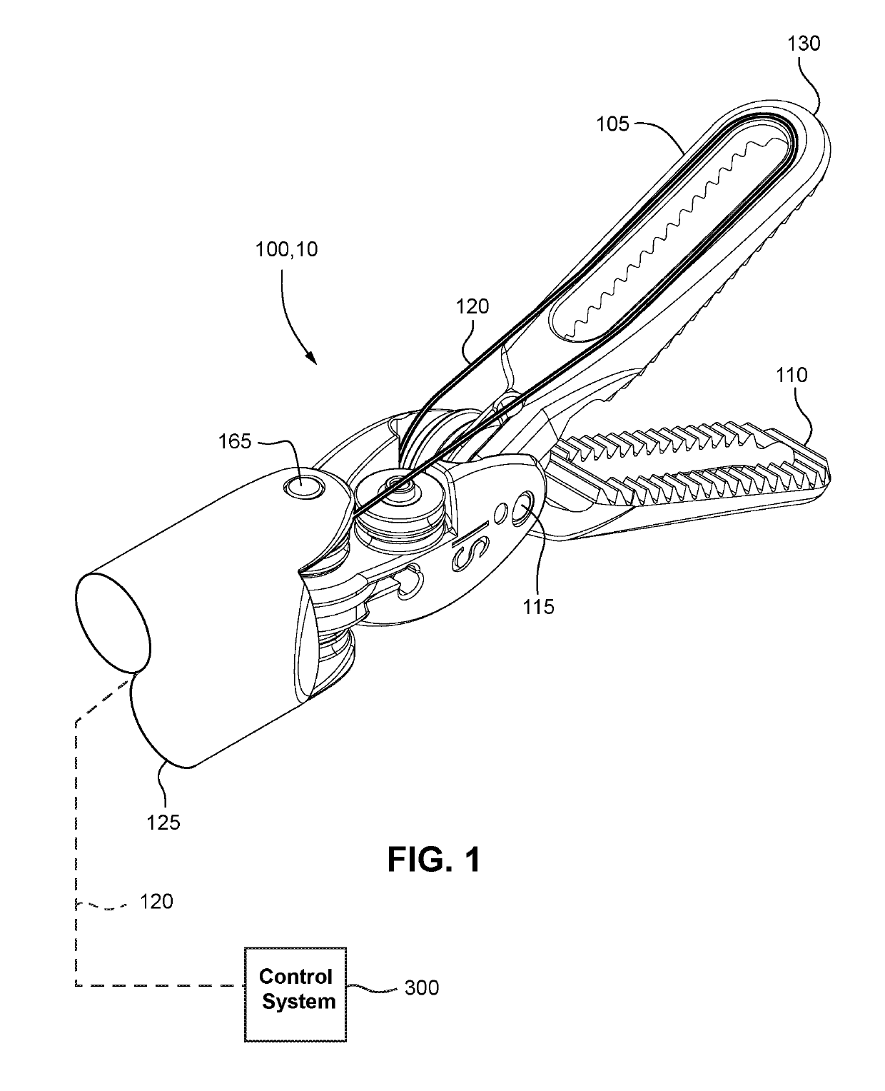
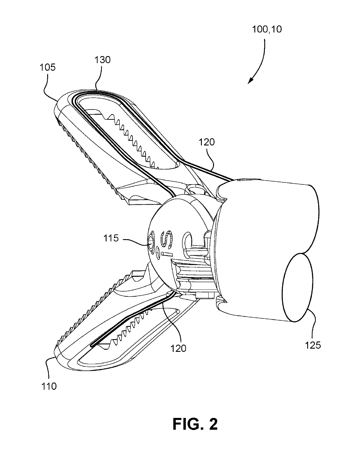
[0012]One or more aspect and examples above may be advantageous. For example, sensing the angle and distributed loading of robotically controlled surgical forceps can allow more precise application of forces to tissue, and reduce trauma to the tissue. Changes in the load profile of the forceps can determine if an object (such as a needle or tissue) is slipping within the forceps. Providing more precise information or other feedback (such as kinesthetic feedback, visual feedback, aural feedback, etc.) may allow less stiff and potentially tougher materials to be used in the construction of the forceps. Precise feedback may also allow a control system to compensate for changes in the mechanical properties of the instrument due to wear, thus extending the useful lifetime of the instrument. The precise measurement of loading and angle may also be used to determine the condition of the instrument, and how much useful life is left in the instrument and / or whether the instrument is safe to use.

Problems solved by technology

But medical instruments, including remotely operated instruments, may lack sufficient sensing capability to provide appropriate tactile feedback.

Method used


Image

  • Fiber optic sensing of tool strain or tool angle
  • Fiber optic sensing of tool strain or tool angle
  • Fiber optic sensing of tool strain or tool angle

Examples


Embodiment Construction

[0030]The following description is provided in relation to several examples which may share common characteristics and features. It is to be understood that one or more features of any one example may be combinable with one or more features of the other examples. In addition, any single feature or combination of features in any of the examples may constitute additional examples.

[0031]As used herein, load is intended to encompass forces (e.g., point loads and distributed loads such as pressure or multiple point loads) acting externally on the tool. For example, if the forceps 100 grips tissue, the tissue will exert a load on the forceps. Strain as used herein should be interpreted as having its ordinary meaning but is typically discussed herein in relation to or as a result of the load applied to the tool or user actuated displacement of the tool. When optical fibers are bent due to an external load or by user commanded movement of the tool, strain will be induced in the optical fibe...


PUM

PropertyMeasurementUnit
forceaaaaaaaaaa
lengthaaaaaaaaaa
areaaaaaaaaaaa

Abstract

A hinged tool includes a first member; a second member pivotally connected to the first member at a pivot; and an optical fiber. The optical fiber is fixed to the first member at a load application region and fixed to at least one of the pivot and the second member at a location such that the optical fiber bends when the first member and the second member are pivoted with respect to one another. A method of using a hinged tool includes measuring fiber strain in an optical fiber fixed to the hinged tool, and determining at least one of tool strain applied to the hinged tool and a degree of pivoting of the hinged tool using the fiber strain.

Description

[0001]This application is claims the benefit of U.S. Provisional Application No. 62 / 383,914 filed Sep. 6, 2016, the entire contents of which is hereby incorporated by reference.BACKGROUND[0002]Various techniques for an optical fiber and applications thereof are known.[0003]For example, the following patents all discuss aspects of detecting the shape of an optical fiber, or the application of such detection: U.S. Pat. Nos. 7,781,724, 7,720,322, 8,460,236, 8,672,837, 8,567,265, U.S. Patent Application Publication No. 2014 / 0121508, U.S. Pat. Nos. 7,050,662, and 5,807,265, all of which are hereby incorporated by reference in their entireties.BRIEF SUMMARY[0004]Precision information and / or tactile or other feedback (such as visual or aural) in medical instruments can be highly desirable. Precision information and / or tactile or other feedback may be even more desirable when operating a medical instrument remotely and interior to a patient's body. For example, tactile or other feedback may...

Claims


Application Information

Patent Timeline
Patent Type & Authority Patents(United States)
IPC IPC(8): G01B11/16G01L1/24A61B34/00G02B6/02A61B90/00
CPCA61B34/76A61B34/70A61B90/06G02B6/02042G01L1/242G01B11/16A61B2090/064A61B2090/067G01L5/0038
Inventor FROGGATT, MARKSANBORN, ERICSANG, ALEXANDER K.WOLFE, MATTHEW S.
Owner INTUITIVE SURGICAL OPERATIONS INC
Why Eureka
Eureka Blog
Learn More