Screwing device and method

A technology of screwing and installing plates, which is applied in the field of mechanical parts processing, can solve problems such as non-skip, redundant processing, and easy deviation, so as to improve accuracy and efficiency, avoid redundant processing, and ensure qualified use.

Active Publication Date: 2019-04-16
HUNAN UNIV OF SCI & ENG
View PDF7 Cites 0 Cited by
  • Summary
  • Abstract
  • Description
  • Claims
  • Application Information

AI Technical Summary

Problems solved by technology

The flexibility of the tightening mechanism in the existing technical scheme is poor, and deviations are prone to occur during the transfer process of tightening different screws, resulting in some screws not functioning normally after being screwed in
In addition, in the existing technology, when the screws are tightened, due to the influence of vibration, the position of the parts is deviated, so that the screws in other positions cannot be screwed in normally.
In addition, in the entire automated screwing process, especially when the product is unqualified in the previous station, when the product is transferred to the screwing station, there is no need to perform screwing action, but the existing technology cannot skip unqualified products , redundant processing occurs

Method used


Image

  • Screwing device and method
  • Screwing device and method
  • Screwing device and method

Examples


Embodiment Construction

[0031] The implementation mode of the present invention is illustrated by specific specific examples below, and those who are familiar with this technology can easily understand other advantages and effects of the present invention from the contents disclosed in this description. Obviously, the described embodiments are a part of the present invention. , but not all examples. Based on the embodiments of the present invention, all other embodiments obtained by persons of ordinary skill in the art without making creative efforts belong to the protection scope of the present invention.

[0032] Terms such as "upper", "lower", "left", "right", "middle", etc. quoted in this specification are only for the convenience of description, and are not used to limit the scope of the present invention. The change or adjustment of the relative relationship shall also be regarded as the implementable scope of the present invention without substantive change of the technical content.

[0033] ...


PUM


Abstract

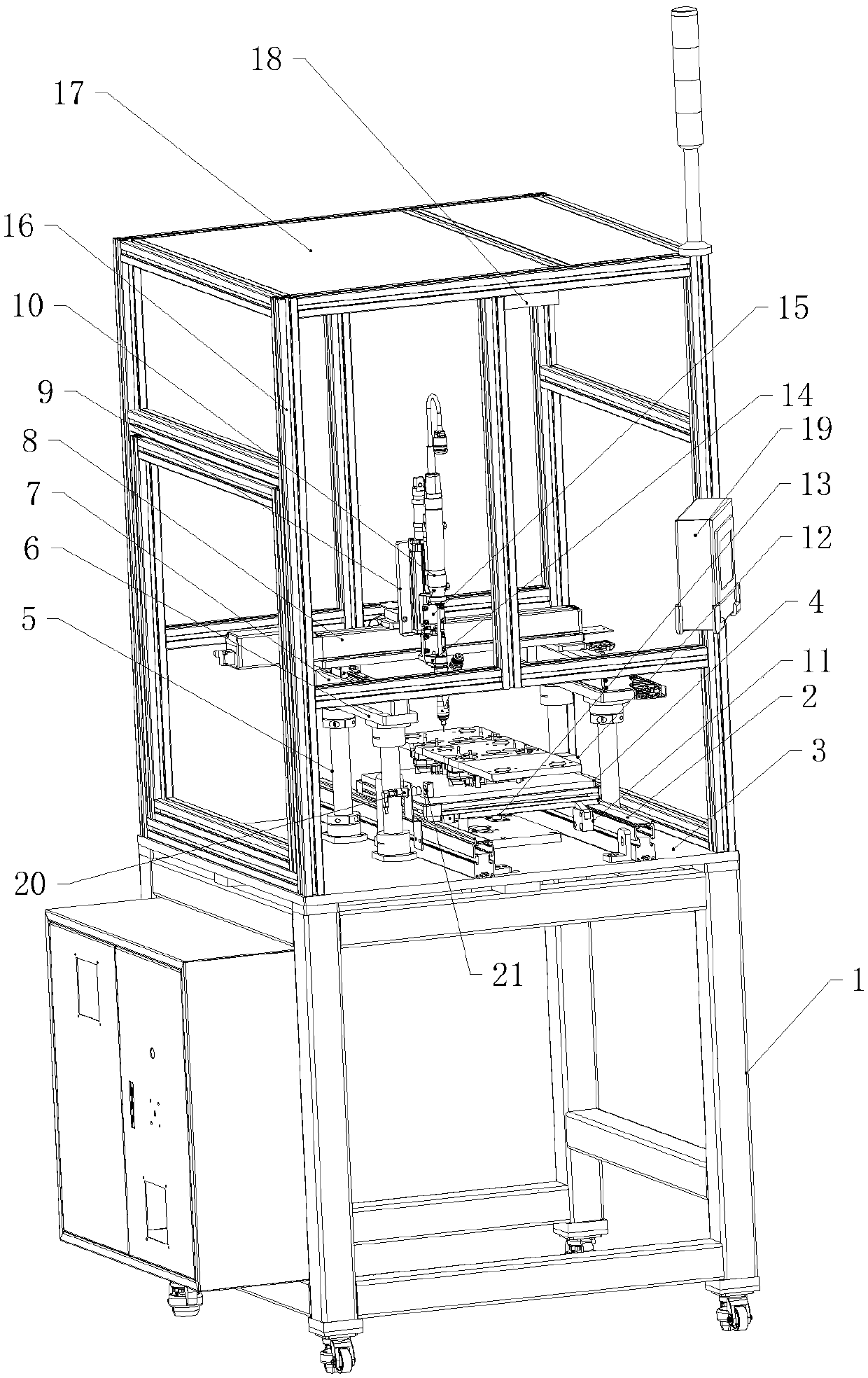
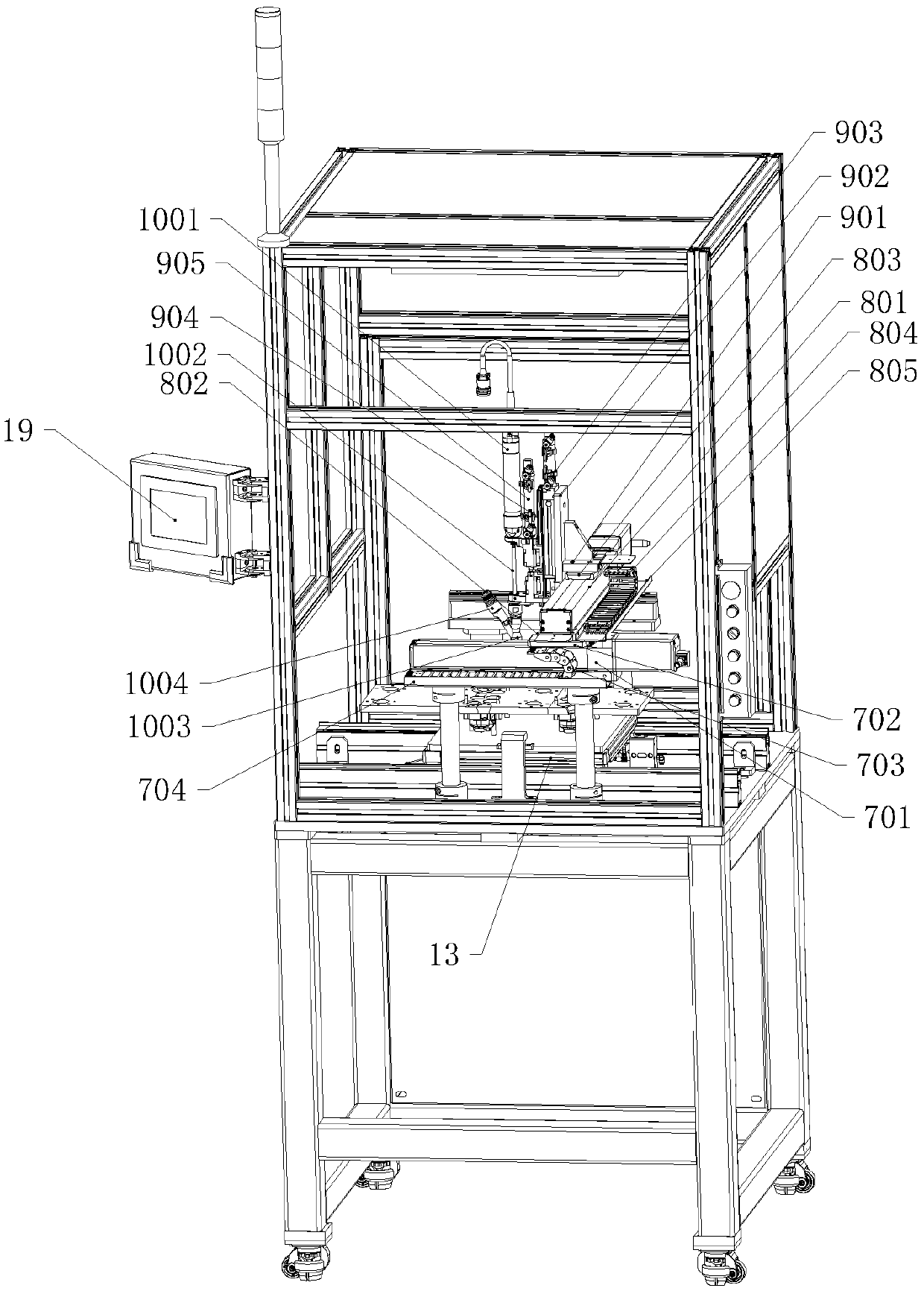
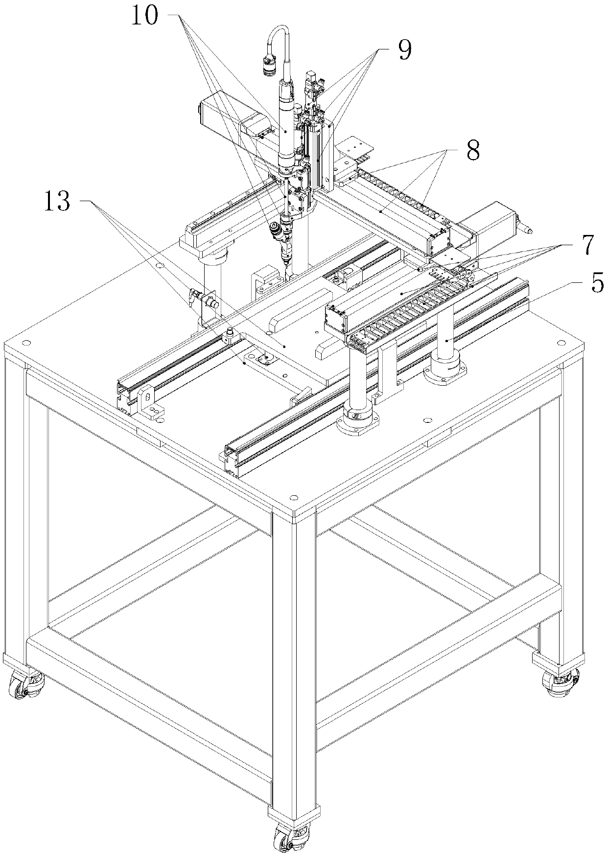
The invention discloses a screwing device and method. A platen is connected to the upper end of a bottom bracket. Conveying rails are erected on the upper part of the platen. A tray is arranged on theconveying rails. Supporting stand columns are connected to the upper end of the platen on two sides of the conveying rails. Parallel plates are arranged at the tops of the supporting stand columns. An X direction moving assembly is arranged on the upper ends of the parallel plates. A Y direction moving assembly is connected to the upper end of the X direction moving assembly. The Y direction moving assembly moves at the upper end of the X direction moving assembly in the X direction. A Z direction moving assembly is arranged on one side of the Y direction moving assembly. The Z direction moving assembly moves on one side of the Y direction moving assembly in the Y direction. A screwing assembly is connected to the inner side of the Z direction moving assembly. The screwing assembly moveson the inner side of the Z direction moving assembly in the Z direction. The screwing assembly is driven by the X direction moving assembly and the Y direction moving assembly to move in the X direction and the Y direction. A stopping mechanism is arranged on the inner sides of the conveying rails. Under limiting by the stopping mechanism, the tray is positioned below the screwing assembly. Accuracy and efficiency of screwing are improved, and qualification and application of products are ensured.

Description

technical field [0001] The embodiments of the present invention relate to the technical field of mechanical parts processing, and in particular to a screw-driving device and method. Background technique [0002] Screws, also known as screws, are tools that use the physical and mathematical principles of the oblique circular rotation and friction of objects to tighten the parts of objects step by step. They are generally made of metal or plastic, cylindrical in shape, and have concave-convex threads engraved on the surface. , Widely used in machinery, electrical appliances and construction fields. [0003] At present, for some parts that need to be tightened by multiple screws on the surface, the flexibility of the tightening mechanism is very important, and it is necessary to be able to accurately locate and apply force according to the specific position of the screw. The flexibility of the tightening mechanism in the existing technical solutions is poor, and deviations are...

Claims


Application Information

Patent Timeline
IPC IPC(8): B23P19/06B23P19/00
CPCB23P19/00B23P19/001B23P19/06
Inventor 李文李强罗哲杨振南何相达秦虎强
Owner HUNAN UNIV OF SCI & ENG
Why Eureka
Try Eureka