
Method for constructing a circuit for fast matrix-vector multiplication

a matrix-vector multiplication and circuit technology, applied in the field of signal processing, can solve the problems of the determination of the delay associated with the adder circuit, and achieve the effect of performing matrix-vector multiplication quickly

Active Publication Date: 2019-03-19
DOURBAL PAVEL
View PDF5 Cites 3 Cited by
  • Summary
  • Abstract
  • Description
  • Claims
  • Application Information

AI Technical Summary

Benefits of technology

The solution enables fast and efficient matrix-vector multiplication, reducing operational complexity and module requirements, allowing for quick processing of digital signals in digital filtering applications.

Problems solved by technology

First, a pipeline delay associated with an adder circuit is determined.

Method used


Image

  • Method for constructing a circuit for fast matrix-vector multiplication
  • Method for constructing a circuit for fast matrix-vector multiplication
  • Method for constructing a circuit for fast matrix-vector multiplication

Examples


Embodiment Construction

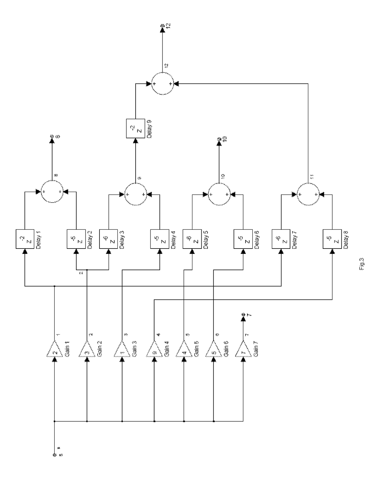
[0041]As can be seen from the below description, the present invention comprises a circuit for performing matrix-vector multiplication. The circuit comprises at least one amplifier component, at least one adder component, and at least one delay component. There are no other electronic components used in creating the circuit.

[0042]The amplifier element that is preferable for practicing the present invention is a digital or analog non-inverting or inverting fixed or variable gain linear electronic signal amplifier; other amplifier elements, such as an optical amplifier or digital multiplier may also be used. The adder element that is preferable for practicing the present invention is a two-input unity gain repeater; other adder elements, such as a non-inverting linear differential amplifier with its inverting input supplied through an inverting amplifier, or an inverting linear differential amplifier with its non-inverting input supplied through an inverting amplifier, or a two-input ...


PUM


Abstract

A circuit for fast matrix-vector multiplication and a method for constructing that circuit are provided, comprising processing a matrix to obtain a pair matrix, which is then used to construct a circuit.

Description

CROSS-REFERENCE TO RELATED APPLICATIONS[0001]The present application is a continuation-in-part of U.S. application Ser. No. 14 / 748,541, filed Jun. 24, 2015, now abandoned which is a continuation of U.S. application Ser. No. 13 / 726,367, filed Dec. 24, 2012, now abandoned which claims priority from U.S. Provisional App. No. 61 / 723,103, filed Nov. 6, 2012. The present application also claims priority from U.S. Provisional App. No. 62 / 502,775, filed May 8, 2017. All of these applications are herein incorporated by reference.BACKGROUNDField of the Invention[0002]The present invention relates generally to signal processing, and more specifically to circuits for performing fast matrix-vector multiplication for purposes of digital filtering or signal filtering with a digital component.Background of the Invention[0003]Digital data often arises from the sampling of an analog signal, for example by determining the amplitude of an analog signal at specific times. The process of converting the a...

Claims


Application Information

Patent Timeline
Patent Type & Authority Patents(United States)
IPC IPC(8): G06F17/16G06J1/00
CPCG06J1/00G06F17/16H03H17/06H04N5/455
Inventor DOURBAL, PAVEL
Owner DOURBAL PAVEL
Learn More