
Self-optimizing hybrid power system

a hybrid power system and self-optimization technology, applied in adaptive control, computer control, instruments, etc., can solve the problems of low system performance, large diurnal and seasonal power fluctuation, and low efficiency of logistics fuel consumption, so as to improve system performan

Active Publication Date: 2019-03-12
THE UNITED STATES OF AMERICA AS REPRESENTED BY THE SECRETARY OF THE NAVY
View PDF29 Cites 5 Cited by
  • Summary
  • Abstract
  • Description
  • Claims
  • Application Information

AI Technical Summary

Benefits of technology

The present invention addresses the inefficiencies in current hybrid power systems' control architectures and provides an inventive method for reducing these inefficiencies through continuously modifying system set points based on predicted data. By maximizing energy production and utilizing renewable energy throughout the system's operational power range, the invention minimizes unnecessary generator starts and excessive generator runtime, resulting in fuel savings and reduced maintenance cycles on system components. The invention also addresses the design challenges associated with commercial and military hybrid power systems by improving system performance and predicting the unknowns that impede or prevent power planning. The self-optimizing hybrid power system is able to create additional, "variable" set points and to plan for anticipated resources, which helps to improve operational efficiency and reliability.

Problems solved by technology

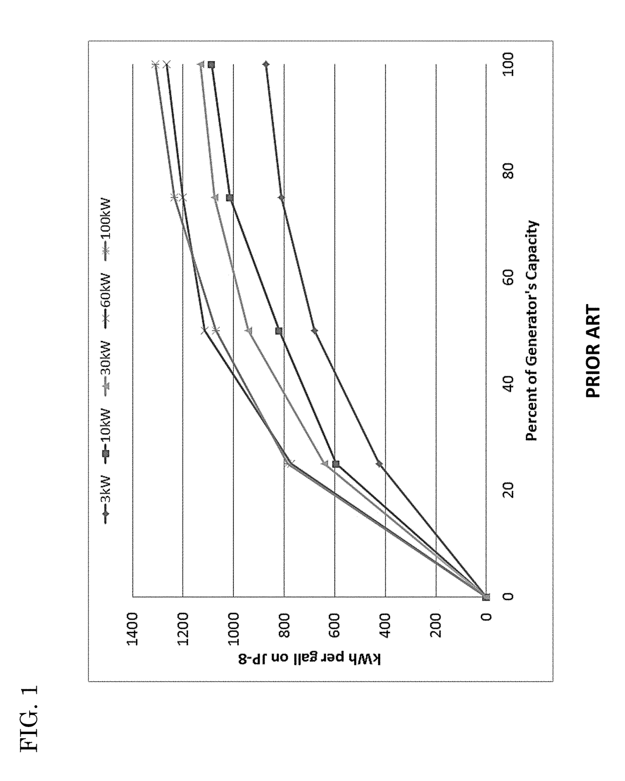
Because of inconsistencies in equipment sets, the drastic diurnal and seasonal power fluctuation inherent to the primary energy consumers, and a limited number of fielded generator sizes, properly sizing a generator to its load becomes very difficult, often resulting in underutilized generators.
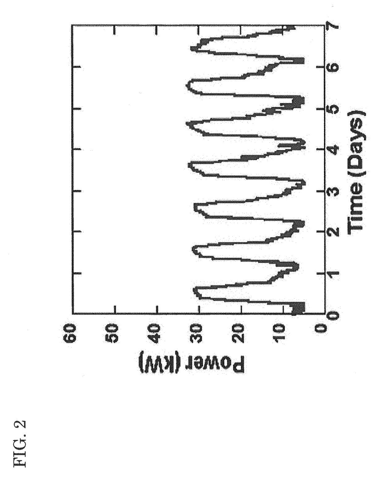
Capability sets such as Combat Operations Centers make up the majority of the loads on the battle field but are inconsistently deployed and have great diurnal and seasonal power fluctuation due to fact that over 70% of their power demand is made up by environmental control systems.
When the generator is not running, the energy storage and any available “free” or renewable energy will be used to support the load, resulting in efficient consumption of logistics fuel and reduced generator maintenance.
Because statistical analysis shows that tactical power systems are often operated at low loads, hybrid power systems provide an operational and economic benefit where they are most typically used; however, significant inefficiencies have been identified in how current hybrid systems use their renewable components.
Conservative thresholds can often cause unintentional cyclic behavior of system components because of operating parameters that hover at or near set point thresholds.
Additionally, current architectures are designed to a specific application or load profile, resulting in inefficient and inconsistent utilization of renewable resources, which is the most important contributor to reaching energy production goals set by the requirements community.
Hybrid power systems that utilize current control system architectures may be able to achieve specific requirement goals set by procurement offices; however, they will not be able to achieve efficient utilization of system resources consistently throughout the systems operating range.
Current systems do not take full advantage of renewable sources, primarily because of: dominance struggles between power sources; unavailability of energy storage to sufficiently store renewable sources when the renewable sources are available; and, conservative set points that may drive fuel burning generators to start unnecessarily.

Method used


Image

  • Self-optimizing hybrid power system
  • Self-optimizing hybrid power system
  • Self-optimizing hybrid power system

Examples


Embodiment Construction

[0042]Reference is now made to FIG. 3, which shows the performance of modeled hybrid power systems using various amounts of renewable energy, in comparison to a standard program-of-record generator. The problem of inconsistent and inefficient utilization of renewable energy is illustrated by the hybrid system modeled with a 3200 W photovoltaic array. When compared to an optimized system with half as much renewable energy, the system with 3200 W of renewables is less efficient at lower loads due to its inability to harvest renewable energy whenever it's available. This is primarily due to the inability of the system to dictate when resources are available and allow sufficient energy storage to accept available renewable sources.

[0043]FIG. 4 illustrates a power source dominance issue, typical of current hybrid power technologies. This problem allows a generator to be the dominate power source when running, causing the “free” renewable resource to be poorly utilized.

[0044]Studies on th...


PUM


Abstract

An exemplary embodiment of the present invention's self-optimizing hybrid power system includes a generator, a solar array, batteries, a GPS, a thermometer, a pyranometer, a power manager, and a computer. The computer: (i) establishes maximum and minimum state-of-charge set points; (ii) receives measurement data from the generator (load), the GPS (location), the thermometer (temperature), and the solar irradiance sensor (solar irradiance); (iii) accesses a historic database that relates to generator load, location, temperature, and solar irradiance; (iv) based on the historic database, predicts a solar profile and a generator load profile; (v) calculates an optimized maximum state-of-charge set point and an optimized minimum state-of-charge set point, based on the predicted solar profile, the predicted generator load profile, the measured location, the measured temperature, and the measured solar irradiance; (vi) transmits control signals to the power manager to vary the maximum and / or minimum state-of-charge set point.

Description

CROSS-REFERENCE TO RELATED APPLICATIONS[0001]This application claims the benefit of U.S. provisional application No. 62 / 234,952, filed 30 Sep. 2015, hereby incorporated herein by reference, entitled “Self-Optimization of Hybrid Power Systems,” joint inventors Evan T. Rule, Eric B. Shields, Crystal P. Lutkenhouse, and John A. Trehubenko.STATEMENT OF GOVERNMENT INTEREST[0002]The invention described herein may be manufactured and used by or for the Government of the United States of America for governmental purposes without payment of any royalties thereon or therefor.BACKGROUND OF THE INVENTION[0003]The present invention relates to hybrid power systems, more particularly to improving efficiencies of hybrid power systems involving renewable energy such as solar power.[0004]The United States Navy is at the forefront of hybrid power systems design. Navy data demonstrates the need for technology development in various respects, including reduction of liquid fuel consumption and of the dan...

Claims


Application Information

Patent Timeline
IPC IPC(8): H02J3/00G05B13/02H02J13/00H02J3/38
CPCH02J3/383H02J13/00G05B13/0205G05B15/02H02J3/38H02J7/34H02J2300/10H02J2300/24H02J3/381Y02E10/56Y04S10/30Y04S10/50Y04S10/123Y02E40/70Y02E60/00
Inventor RULE, EVAN T.SHIELDS, ERIC B.LUTKENHOUSE, CRYSTAL P.TREHUBENKO, JOHN A.
Owner THE UNITED STATES OF AMERICA AS REPRESENTED BY THE SECRETARY OF THE NAVY
Learn More