
Method for fabricating superconducting devices using a focused ion beam

a superconducting device and focused ion beam technology, applied in the direction of superconducting device magnitude/direction, magnetic field measurement using superconducting device, semiconductor device, etc., can solve the problems of difficult processing of hts materials, disrupting superconductivity, electrical properties of josephson junction sensitive to chemical changes and structural defects, etc., to achieve the effect of increasing the ion fluen

Active Publication Date: 2019-03-05
RGT UNIV OF CALIFORNIA
View PDF20 Cites 3 Cited by
  • Summary
  • Abstract
  • Description
  • Claims
  • Application Information

AI Technical Summary

Benefits of technology

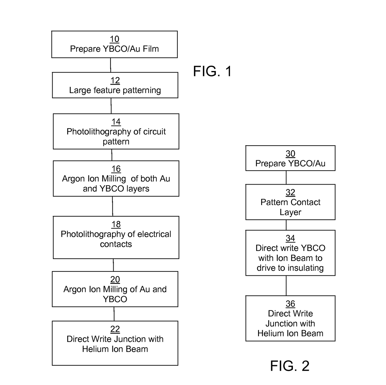
[0011]In an exemplary embodiment, high-quality all-HTS Josephson superconducting tunnel junctions, arrays and superconducting quantum interference devices (SQUIDs) can be created by using a sub-nanometer focused beam of ions to direct-write insulating barriers into superconducting thin films such as YBa2Cu3O7-δ (YBCO). In some embodiments, a focused helium ion beam, with its diameter of around 500-pm, which is on the order of the tunneling length, allows the electrical transport properties of the Josephson barriers to be continuously tuned from metallic to insulating by merely increasing the ion fluence. In other embodiments, Josephson junctions may be fabricated in different superconducting films, including magnesium diboride, iron pnictides (e.g., Fe—As), or materials that are sensitive to disorder, such as multiferroics, graphene, manganites and semiconductors. Other ion beams with similar characteristics may be used, for example, focused silicon or beryllium ion beams, with beam diameters of 8 and 5 nm, respectively.
[0012]The inventive technique allows tuning of the junction characteristics and enables reproducible and scaled-up production of superconducting Josephson devices that can operate at easily-accessible temperatures, e.g., at or above 77 K. The invention has potential for far reaching impact on applications of superconducting electronics, from highly sensitive magnetometers for biomagnetic measurements of the human body, to large scale arrays for wideband satellite communications.
[0018]In order to achieve the desired performance and repeatability, the thickness of the superconducting film must be carefully controlled to be less than or equal to 30 nm so that uniform irradiated regions can be created. The irradiated Josephson junction regions are very narrow (about a nanometer, or less than the superconducting coherence length) and have electrical properties that differ greatly from those of wider regions. Ion fluences ranging between 1014 and 1018 He+ / cm2 were used. In between these two extremes, doses were determined to create very high-quality Josephson junctions and continuously transition, from “SNS” junctions to “SIS” Josephson tunnel junctions. The doses were delivered in a one-dimensional line rather than a two-dimensional area to avoid overlap of defects from lateral straggle and make the defect barrier as narrow as possible. These techniques lead to excellent junction uniformity and electrical properties, including significant expansion of the operating temperature window. Additional improvements can obtained (e.g., further increasing the figure of merit ICRN) by using higher energy beams to create even narrower barriers that will increase IC considerably. Currently, gas field helium ion sources are limited to ˜30 kV because this is the optimum extraction energy, however a negative bias could be added to the substrate to effectively increase the irradiation energy. Higher energies would also allow use of thicker films which have higher critical currents and better magnetic screening capability.

Problems solved by technology

A challenge associated with reaching these goals is that HTS materials are difficult to process and the superconducting coherence length is both short and anisotropic, typically ˜2 nm in the a-b plane and ˜0.2 nm along the c-axis.
The coherence volume encloses very few superconducting pairs, so even the presence of small scale inhomogeneities can disrupt superconductivity.
As a result, the electrical properties of Josephson junctions are sensitive to chemical changes and structural defects on atomic length scales.
This further complicates device fabrication because the highest quality HTS films have c-axes oriented normal to the substrate.
This complicates the possibility of growing epitaxial multi-layers to form sandwich-type junctions such as those created from conventional superconductors like niobium.
Unfortunately, these junctions have poor uniformity, limited scalability, and can only be made on small substrates.
In addition, device fabrication is neither widely uniform nor predictable, and is more of an art-form than a manufacturable process.
Another drawback to these ion irradiated Josephson junctions is the presence of a large non-Josephson excess current at zero voltage that does not exhibit either the DC or AC Josephson effects.
This dimension is too challenging for most nanofabrication techniques such as electron beam lithography or gallium focused ion beams, which were not capable of creating a narrow (˜1 nm) and strong barrier.

Method used


Image

  • Method for fabricating superconducting devices using a focused ion beam
  • Method for fabricating superconducting devices using a focused ion beam
  • Method for fabricating superconducting devices using a focused ion beam

Examples


example 1

NS Junction

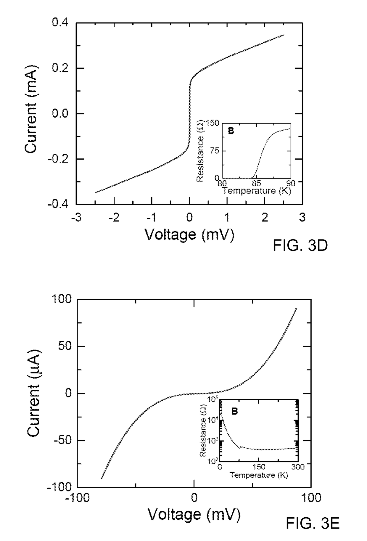
[0060]The current voltage characteristics (I-V) are shown in FIG. 6A for a typical SNS Josephson junction measured for several temperatures. They were fit with integral form of the Ambegaokar-Halperin (A-H) model (V. Ambegaokar, B. I. Halperin, Phys. Rev. Lett. 23, 274 (1969)), and with the addition of added excess current determined by suppressing the Josephson current with magnetic field (FIG. 6B). From the fits, one can determine IC, RN, and the noise temperature TN. Including Iχ in these fits is essential to obtain realistic values of ICRN, which are almost always incorrectly overestimated in analysis of YBCO junctions because of the inclusion of excess current in the estimate of IC.

[0061]FIG. 6C shows the fitted IC and RN values as functions of temperature. The noise temperature of the measurement system was found to be 130 K. The decrease in resistance as temperature is lowered indicates the barrier is a conductor. The resistance ˜1Ω is roughly 10× larger than typic...

example 3

Uniformity—SNS Array

[0066]To further test the uniformity the helium ion beam junctions, arrays of closely spaced junctions connected in series were constructed by scribing multiple lines across the bridge. FIG. 9A shows I-V for several temperatures of a 20 junction SNS series array with inter junction spacing of 500 nm. The arrays exhibit much less rounding near the critical current than previously reported Josephson arrays suggesting very good uniformity of ICRN.

[0067]This high level of uniformity is also apparent when characterizing the array using the AC Josephson effect. FIG. 9B shows a 20 junction array irradiated with RF from an open circuited coax cable at 17.6 GHz. A large pronounced flat giant Shapiro step is observed at

[0068]20×hf2⁢e=0.727⁢⁢mV,

suggesting that the fundamental voltage step for each junction within the array is occurring at the same bias current. This situation will only occur if the resistances are nearly the same. A series array of 20 SIS junctions was also...

example 4

Uniformity—SIS SQUID Array

[0069]An array of SIS junction SQUIDs was also fabricated. Five rectangular superconducting loops each with area 12×4 μm2 connected in parallel were patterned using the same process described above except the film was slightly thicker ˜35 nm. The I-V and its derivative are shown in FIG. 10A. As with the other tunnel junction devices, the SQUID also exhibits conductance peaks at 24=32 mV. The array was biased with a static current of 120 μA and the voltage was measured as a function of magnetic field and the resulting Fraunhofer and SQUID oscillations are shown in FIG. 10B. The Fraunhofer pattern shows self-field asymmetry in magnetic field like the single junctions with larger critical currents. The SQUID pattern exhibits a periodicity of 25 μT and a modulation depth of 40 μV (FIG. 10C). Based on the ratio of the two patterns (˜50%), the inductive parameter βL=2LIC / Φ0 was estimated to be equal to 1.0. This yields a very large value for the inductance L=0.5 ...


PUM


Abstract

Nano-scale junctions, wires, and junction arrays are created by using a focused high-energy ion beam to direct-write insulating or poorly conducting barriers into thin films of materials that are sensitive to disorder, including superconductors, ferromagnetic materials and semiconductors.

Description

RELATED APPLICATIONS[0001]This application is a 371 national stage filing of International Application No. PCT / US2015 / 035426, filed Jun. 11, 2015, which claims the benefit of the priority of U.S. Provisional Application No. 62 / 010,991, filed Jun. 11, 2014, each of which is incorporated herein by reference in its entirety.GOVERNMENT RIGHTS[0002]This invention was made with government support under Contract No. DEAC02 05CH11231 from the United States Department of Energy. The government has certain rights in the invention.FIELD OF THE INVENTION[0003]The present invention relates to superconducting devices and a method for fabricating such devices and more specifically to use of a sub-nanometer ion beam to reproducibly produce superconducting tunneling devices that can operate within the HTS realm.BACKGROUND[0004]Since the discovery of the high-transition-temperature superconductors (HTS), researchers have searched for a method to fabricate superconducting tunnel junctions from these m...

Claims


Application Information

Patent Timeline
Patent Type & Authority Patents(United States)
IPC IPC(8): G01R33/035H01L27/18H01L39/24
CPCH01L39/2496H01L39/2493H01L39/249H01L27/18H10N69/00H10N60/0884H10N60/0941H10N60/0912
Inventor CYBART, SHANE A.CHO, ETHAN Y.DYNES, ROBERT C.WONG, TRAVIS J.
Owner RGT UNIV OF CALIFORNIA
Learn More