
Positioning device for radio frequency matcher

a technology of positioning device and radio frequency matcher, which is applied in the direction of frequency control by mechanical means, resonant circuit using central processing unit, instruments, etc., can solve the problems of not being able to determine whether the radio frequency load is high or low, and achieve the effect of maximizing the power of the radio frequency load of the radio frequency matcher

Active Publication Date: 2019-02-19
FAIRTECH
View PDF2 Cites 0 Cited by
  • Summary
  • Abstract
  • Description
  • Claims
  • Application Information

AI Technical Summary

Benefits of technology

The patent aims to provide a device that helps position the tuning elements of a radio frequency matcher to ensure maximum power is being sent to the load. The device interprets signals from detecting elements and outputs the information in a user-friendly way to show if the moving parts are in the correct place.

Problems solved by technology

However, because the impedance of the load is variable, there must be occasions when the load does not match the signal source so that the load does not achieve a highest possible power and a power signal that is reflected to the signal source is generated.
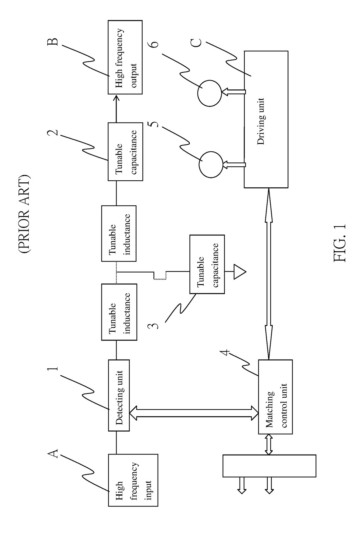
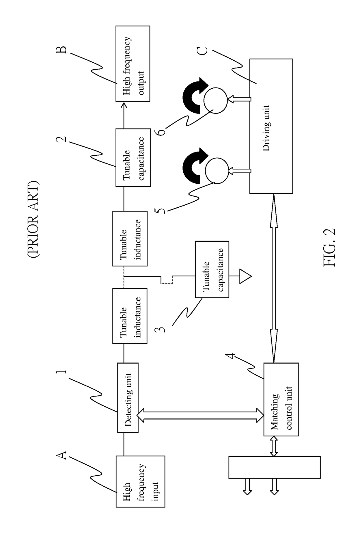
When the electric motors 5 and 6 of a conventional radio frequency matcher drive the tunable capacitance 2 and tunable capacitance 3, there is no way for a user to know whether they have been adjusted to right positions, and therefore there is no way to determine whether the radio frequency load has achieved a highest possible power.

Method used


Image

  • Positioning device for radio frequency matcher
  • Positioning device for radio frequency matcher
  • Positioning device for radio frequency matcher

Examples


Embodiment Construction

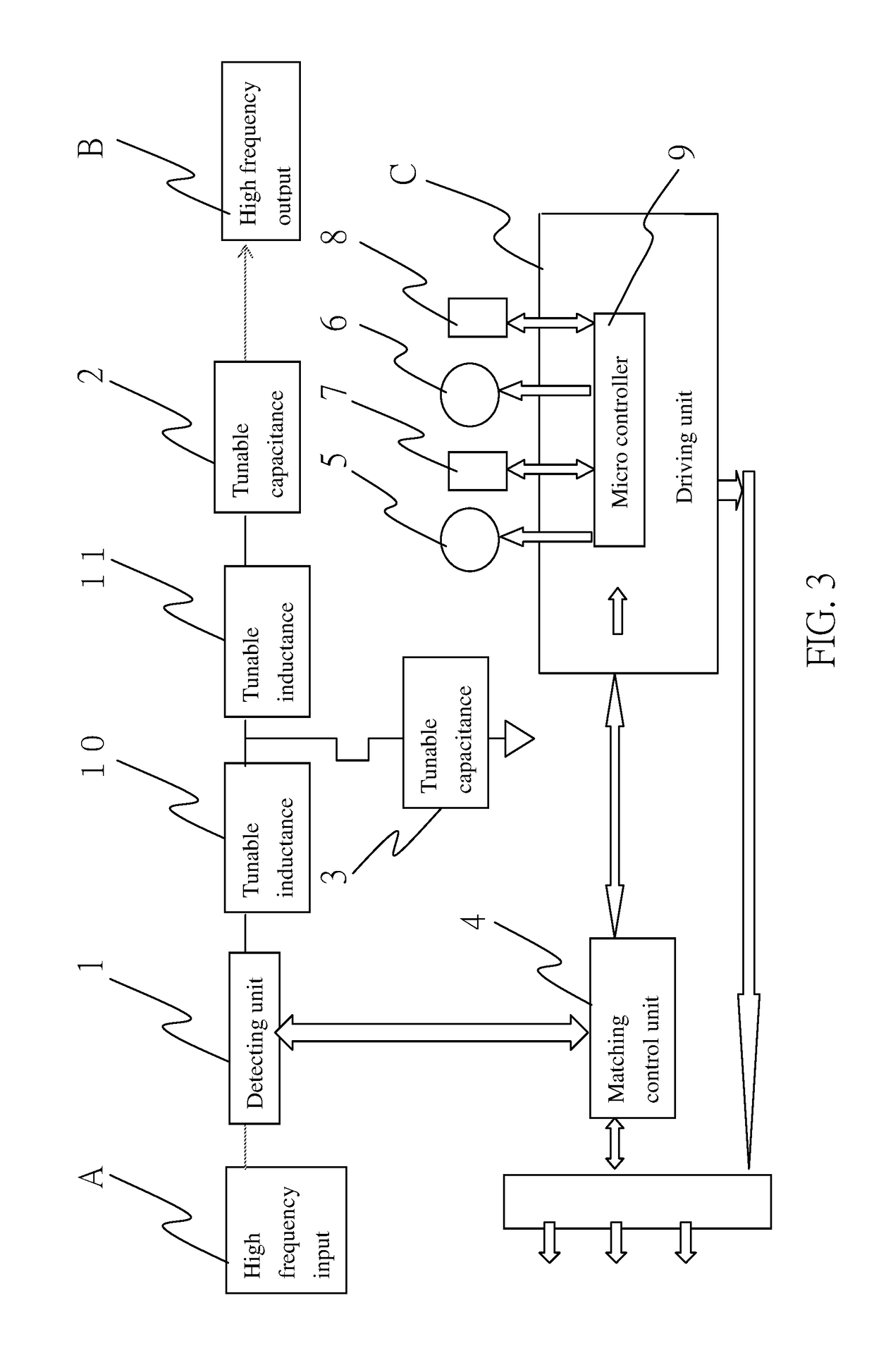
[0011]Please refer to FIG. 3, showing a block diagram of an electric circuit of a preferred embodiment according to the present invention. As the figure shows, same as a conventional radio frequency matcher, the present invention is provided with a detecting unit 1 for detecting radio frequency input A, wherein the detecting unit 1 is connected to two tuning elements for forming radio frequency output B. The two tuning elements are two special tunable electrical reactance elements, tunable capacitance 2 and tunable capacitance 3. The detecting unit 1 is connected to a matching control unit 4. One of the two electric motors 5 and 6 drives the tunable capacitance 2 or tunable inductance 10, while the other drives the tunable capacitance 3 or tunable inductance 11. The electric motors 5 and 6 adjust the positions of the moving pieces of the two tuning elements (tunable capacitance 2 and 3 or tunable inductance 10 and 11) via a driving unit C based on the volume of two error signals to ...


PUM


Abstract

A positioning device for a radio frequency matcher comprises mainly a micro controller, and at least two detecting elements connected to the micro controller. The detecting elements are disposed on electric motors to detect the rotation angles of the electric motors. When the electric motors adjust the positions of the moving pieces of the tuning elements based on the volume of error signals to change the electrical reactance values so that they may approximately meet the requirement of the radio frequency load and that the radio frequency load may achieve a highest possible power, the micro controller may interpret the signals of the rotation angle detecting elements and output the interpreted values for a user to determine whether the moving pieces of the tuning elements are at right positions to approximately meet the requirement of the radio frequency load and maximize the power of the radio frequency load of the radio frequency matcher.

Description

BACKGROUND OF THE INVENTION1. Field of the Invention[0001]The present invention relates to a positioning device for a radio frequency matcher, and particularly to a positioning device for a radio frequency matcher which interprets signals of detecting elements and outputs the interpreted values for a user to determine whether the moving pieces of tuning elements are at right positions to maximize the power of the radio frequency load of the radio frequency matcher.2. Description of Related Art[0002]As FIG. 1 and FIG. 2 show, a conventional positioning device for a radio frequency matcher usually comprises a detecting unit 1 for detecting radio frequency input A, wherein the detecting unit 1 is connected to two tuning elements for forming radio frequency output B. The two tuning elements are two special tunable electrical reactance elements, tunable capacitance 2 and tunable capacitance 3. The detecting unit 1 is connected to a matching control unit 4. In a transmission path, radio f...

Claims


Application Information

Patent Timeline
Patent Type & Authority Patents(United States)
IPC IPC(8): H03H7/40H03J7/16
CPCH03J7/16H03H7/40H03J1/0008H03J1/06H02K11/21G01R1/0408G01R23/02G01R31/2836G01R31/2839G01R31/34
Inventor PAN, JUI-PAO
Owner FAIRTECH
Learn More