Vacuum ejector with multi-nozzle drive stage and booster

a technology of vacuum ejector and drive stage, which is applied in the direction of machines/engines, non-positive displacement pumps, mechanical equipment, etc., to achieve the effects of less space requirements, faster response times, and high vacuum

Inactive Publication Date: 2019-02-12
PIAB
View PDF160 Cites 4 Cited by
  • Summary
  • Abstract
  • Description
  • Claims
  • Application Information

AI Technical Summary

Benefits of technology

[0027]The invention offers the choice of generating a higher vacuum at quicker response times and less space requirements in a more versatile manner.

Problems solved by technology

Although such multi-stage ejector arrangements are beneficial in providing both a high-volume flow rate and a high level of negative pressure, there is necessarily still some degree of compromise in the design of each successive stage in the ejector, in order to obtain an overall desired performance characteristic for the multi-stage ejector as a whole.

Method used


Image

  • Vacuum ejector with multi-nozzle drive stage and booster
  • Vacuum ejector with multi-nozzle drive stage and booster
  • Vacuum ejector with multi-nozzle drive stage and booster

Examples


first embodiment

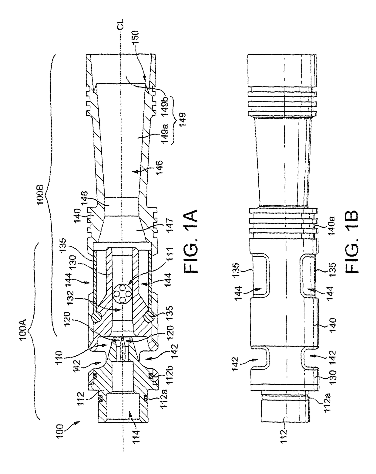
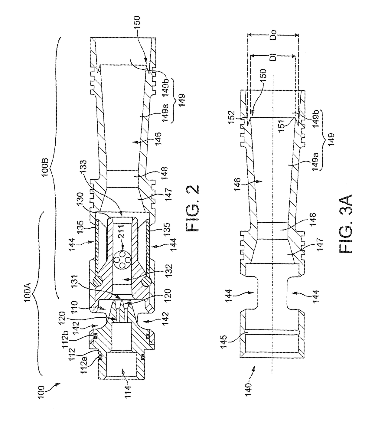
[0050]FIGS. 1A and 1B show an ejector according to the present invention. The embodiment of FIGS. 1A and 1B is configured as an ejector cartridge 100. Such a cartridge is intended to be installed within an ejector housing module, or within a bore or chamber formed in an associated piece of equipment, which defines the volume to be evacuated by the ejector cartridge.

[0051]Although the most preferred embodiment of the ejector, as shown in the drawings, is designed to work with air as the drive fluid, and as the fluid to be evacuated, the ejector will be applicable to any gas as the drive fluid, and any gas as the fluid to be evacuated. The drive fluid will have a primary direction of movement, or flow, through the ejector. This direction is parallel to the longitudinal axis of the ejector, shown horizontally in the drawings, and starting from the inlet 114. In the following, this direction will be referred to as the direction of airflow.

[0052]Ejector cartridge 100 is a multi-stage eje...

second embodiment

[0082]Turning to FIGS. 5A, 5B, 6, 7A to 7C and 8, there is shown an ejector according to the present invention. The embodiment of FIGS. 5A, 5B, 6, 7A to 7C and 8 is also configured as an ejector cartridge 200.

[0083]The ejector 200 is similar in construction and operation to the ejector 100, and the description above of the features, components, operation and use of the ejector 100 applies equally to the ejector 200, except where further features or variations are particularly explained. Again, ejector cartridge 200 includes a first, drive stage 200A and a second stage 200B.

[0084]FIG. 5B is an axial end view, facing towards the exit end of the ejector 200, which clearly shows the outlets of the drive nozzles 220 arranged in a grouping so as to face into and along the axial passage defined by the second stage nozzle 232 and the exit nozzle 246. FIG. 5A shows the section A-A of FIG. 5B, which contains the centre axis CL, about which the ejector cartridge 200 substantially forms a body ...


PUM


Abstract

An ejector system includes a primary ejector in a drive stage and a booster ejector connected in parallel with the primary ejector for simultaneously generating a vacuum across a booster stage. The booster ejector may be configured to generate a vacuum to a lower pressure in the booster stage than in the primary ejector in the drive stage. The booster stage and the drive stage may be connected to a common volume to be evacuated and a valve may be provided to close the connection between the drive stage and the volume to be evacuated when the pressure in the volume to be evacuated falls below the minimum pressure that can be generated in the drive stage.

Description

PRIORITY[0001]This application is a U.S. national stage application of International Application No. PCT / EP2013 / 077122, filed Dec. 18, 2013, which claims priority to United Kingdom Application No. 1223418.3, filed Dec. 21, 2012, each of which is incorporated by reference in its entirety into this application.TECHNICAL FIELD[0002]The present invention relates to vacuum ejectors driven by compressed air.BACKGROUND ART[0003]Vacuum pumps are known which use a source of compressed air (or other high-pressure fluid) in order to generate a negative pressure or vacuum in a surrounding space. Compressed-air driven ejectors operate by accelerating the high pressure air through a drive nozzle and ejecting it as an air jet at high speed across a gap between the drive nozzle and an outlet flow passage or nozzle. Fluid medium in the surrounding space between the drive nozzle and outlet nozzle is entrained into the high-speed flow of compressed air, and the jet flow of entrained medium and air ori...

Claims


Application Information

Patent Timeline
Patent Type & Authority Patents(United States)
IPC IPC(8): F04F5/22F04F5/46F04F5/54
CPCF04F5/22F04F5/54F04F5/466
Inventor TELL, PETER
Owner PIAB
Why Eureka
Try Eureka