Conveyor device

a conveyor and a technology of a conveyor, applied in the direction of conveyor parts, packaging, transportation and packaging, etc., can solve the problems of excessive contact with the article, excessive twisting of the infilling member, and large clearance, so as to prevent an extremely large clearance, prevent the twisting and prevent the damage of the infilling member

Active Publication Date: 2019-02-12
DAIFUKU CO LTD
View PDF20 Cites 3 Cited by
  • Summary
  • Abstract
  • Description
  • Claims
  • Application Information

AI Technical Summary

Benefits of technology

[0015]According to the conveyor device of the present invention, the pivot (swing shaft) for vertically swinging the infilling member is shifted in a direction opposite to the traveling direction of the travel unit from the position of the coupler connecting the travel units. This can suppress the twisting of the infilling member on a curve of the conveying path, prevent the infilling member and the article support from unnecessarily coming into contact with each other, and prevent an extremely large clearance from being left between the infilling member and the article support. Thus, damage to the infilling member can be prevented on a curve of the conveying path.

Problems solved by technology

In the conveyor device according to the related art, however, when the article support and the infilling member travel on a curve of a conveying path in a tilted position (For example, if an article is discharged to a chute provided on a curve of the conveying path or if the article support and the infilling member are tilted to discharge an article to a chute provided on a linear part of the conveying path and then the article support and the infilling member do not recover from the tilted position due to some malfunctions), the infilling member may be twisted and excessively come into contact with the article support or an extremely large clearance may be left between the infilling member and the article support.

Method used


Image

  • Conveyor device
  • Conveyor device
  • Conveyor device

Examples


Embodiment Construction

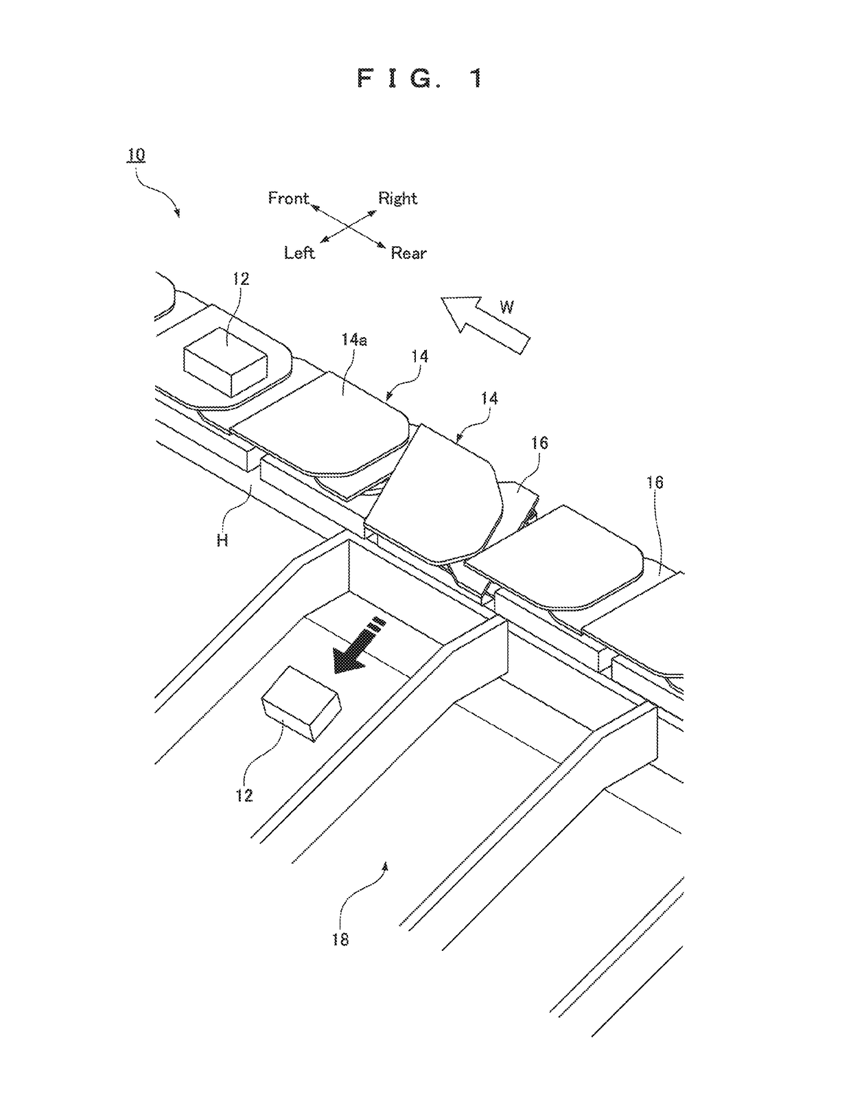
[0020]A conveyor device 10 will be described as an example of an embodiment of the present invention. In the following explanation, a conveying direction W of an article 12 to be conveyed by the conveyor device 10 (the traveling direction of a travel unit 20) will be described as the front-and-rear direction of the conveyor device 10, whereas a horizontal direction crossing the conveying direction W of the article 12 will be described as the lateral direction of the conveyor device 10.

[0021]As shown in FIGS. 1 and 2, the conveyor device 10 mainly includes a plurality of trays 14 (an example of “article support”) that support articles 12, a plurality of infill plates 16 (an example of “infilling member”) that are provided for the respective trays 14 so as to cover clearances left between the trays 14, and a plurality of travel units 20 that travel along a conveying path H of the articles 12. In the conveyor device 10, the article 12 placed on the tray 14 is conveyed in the conveying ...


PUM


Abstract

A conveyor device for conveying articles includes: travel units, trays provided for the respective travel units, and infill plates, each covering a clearance left between the trays. A swing bar supports the infill plate so as to vertically swing the infill plate and is provided at a position shifted by a predetermined distance L in a direction opposite to the traveling direction of the travel unit from the position of a coupler connecting the travel unit supporting a plate-tilting shaft and the travel unit traveling ahead, the plate-tilting shaft supporting the infill plate so as to laterally tilt the infill plate.

Description

FIELD OF THE INVENTION[0001]The present invention relates to a conveyor device for conveying articles and particularly relates to a conveyor device including article supports such as trays that are provided on their respective travel units so as to travel on a conveying path.BACKGROUND OF THE INVENTION[0002]A conveyor device according to the related art includes article supports such as trays that are provided on their respective travel units so as to travel on a conveying path. In such a conveyor device, a clearance is left between the adjacent article supports. The clearance is covered with an infilling member such as a cover, thereby preventing an article from being dropped or caught into the clearance. For example, in WO 00 / 02802 (“Patent Literature 1”), a cover member (infilling member) is slidably attached to the underside of an article support so as to cover a gap (clearance) left between the article supports of adjacent conveyor units.[0003]In the conveyor device, the articl...

Claims


Application Information

Patent Timeline
Patent Type & Authority Patents(United States)
IPC IPC(8): B65G47/40B65G47/96B65G17/34
CPCB65G47/40B65G17/345B65G47/965B65G2207/18B65G2201/02B65G17/32B65G47/962B65G17/066
Inventor FUJIO, YOSHIHIKO
Owner DAIFUKU CO LTD
Why Eureka
Try Eureka